
Method and apparatus of distributed plasma processing system for conformal ion stimulated nanoscale deposition process

a technology of conformal ion and nanoscale deposition, applied in the field of conformal thin film deposition methods and apparatuses, can solve the problems of affecting the overall yield, affecting the coverage of the step, and the requirement of deposition becoming more critical, and achieves the effect of improving the coverage characteristics and high aspect ratio features

Inactive Publication Date: 2008-01-31
TOKYO ELECTRON LTD
View PDF40 Cites 373 Cited by
  • Summary
  • Abstract
  • Description
  • Claims
  • Application Information

AI Technical Summary

Benefits of technology

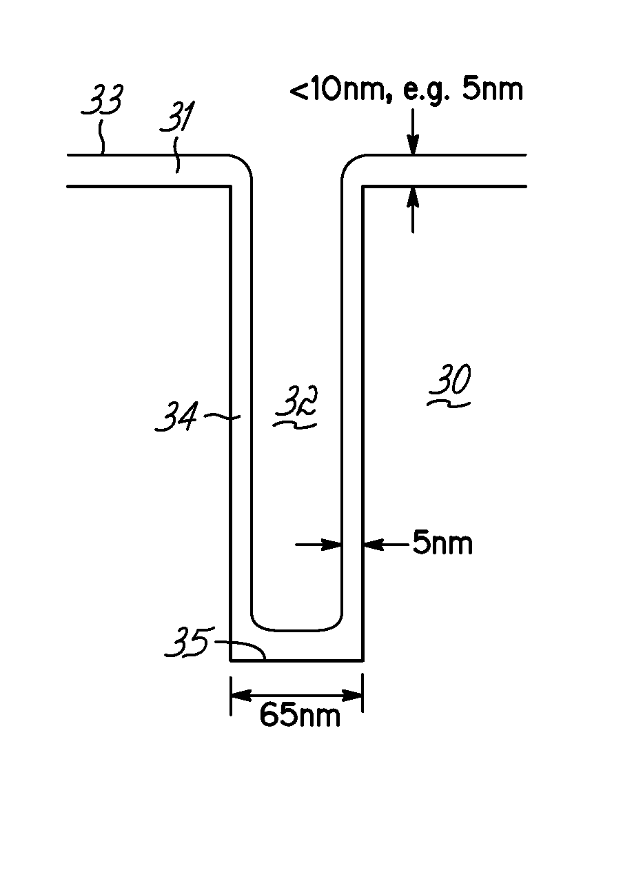
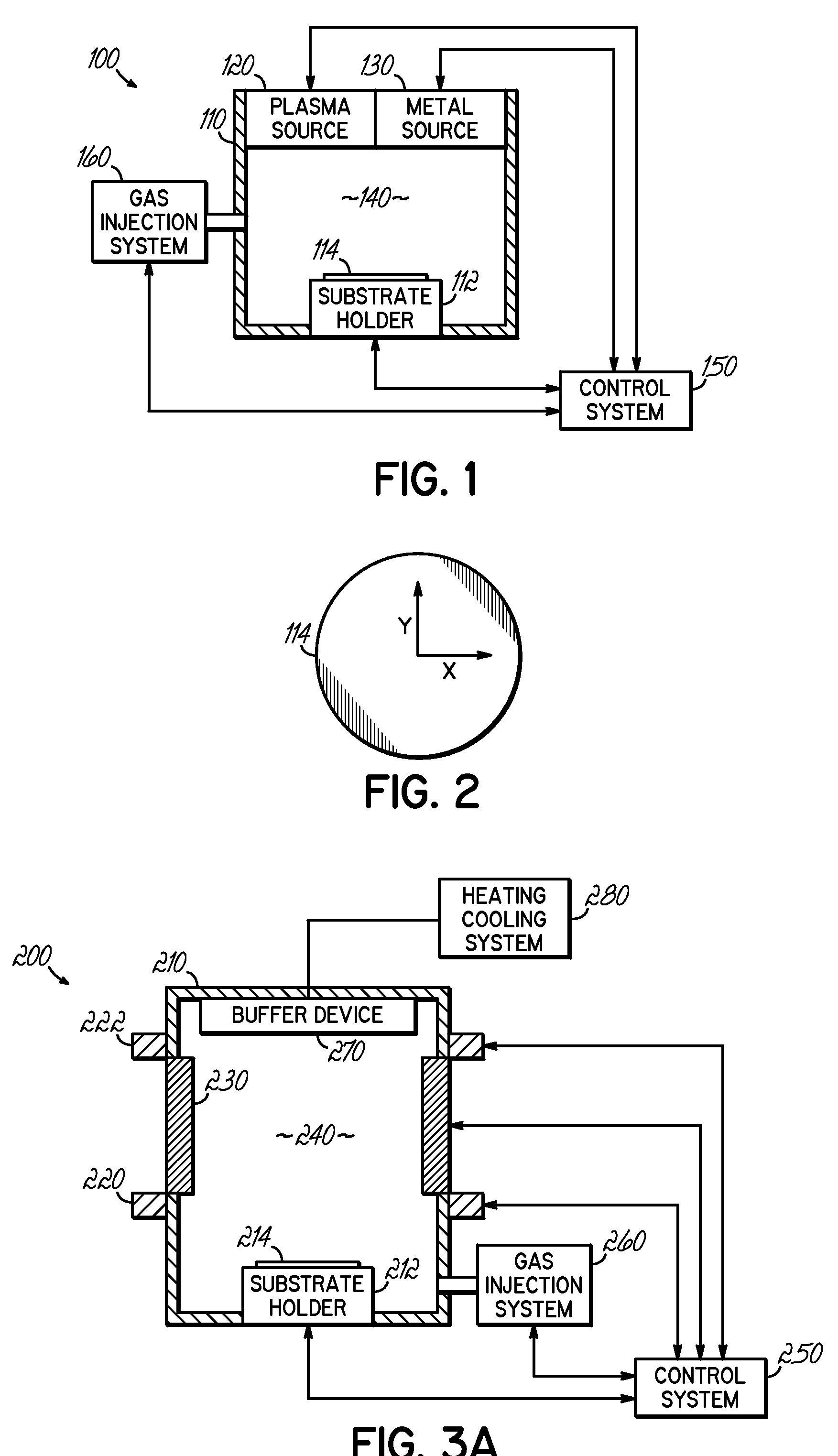
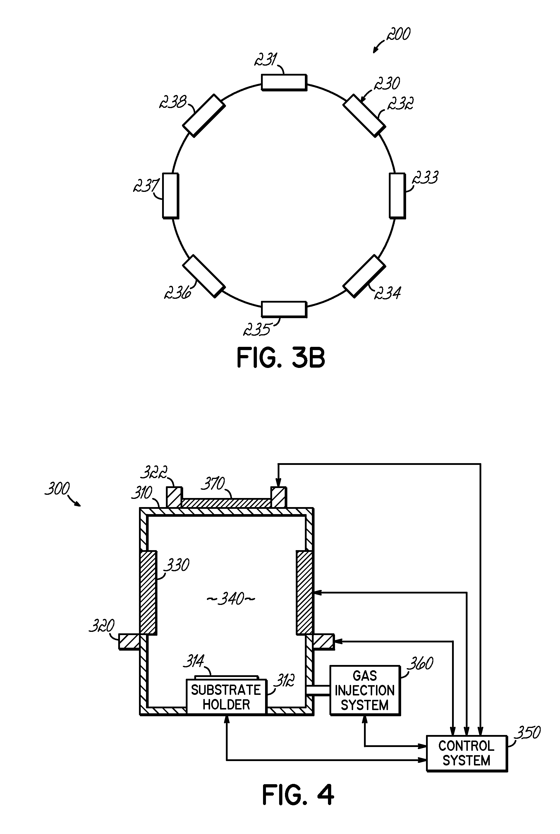
The present invention provides a method and system for depositing a thin film in high aspect ratio features on a substrate. The system includes a process chamber, a substrate holder, a plasma source, and a metal source. The plasma source and metal source are configured to produce a ratio between metal density and plasma density of less than unity above the substrate. This ratio is important for achieving conformal deposition within the feature on the substrate. The invention can be used for depositing films of other coating materials that have lower ionization potentials than the background processing gas. The technical effects of the invention include improved coverage characteristics within high aspect ratio features and reduced deposition time.

Problems solved by technology

Ionized PVD has provided good sidewall and bottom coverage in via and trench structures; however, the deposition requirements become more critical as geometries shrink and as via dimensions fall below approximately 100 nanometers.
Furthermore, the creation of overhang has also been identified to be sensitive to the feature shape, and this effect has an impact on the overall yield of the process.
Generally, a conformal deposition of the thin layers in interconnect fabrication has been very difficult with current conventional processing and, hence, it has yielded very poor step coverage, which is sometimes defined numerically as the ratio of feature sidewall coverage thickness to coverage thickness in the field area or horizontal surface of the substrate below which the feature extends, with a higher ratio, approaching unity, being better.
However, the inventor has observed that conventional process conditions still result in some undesirable effects, which may include overhang and closure of via, discontinuity of the metal layer, low deposition rate, and throughput limitations.
With some approaches, independent deposition and etch systems may be required, which involve substrate transfer issues, contamination can occur due to an unprotected internal coil, and non-uniform plasma generation and consequently non-uniform etching are just a few additional issues facing current practice.
Moreover, the inventor has observed that consideration of only the re-sputtering effect at the substrate surface does not completely prevent overhang build-up.
Thus, while somewhat improved relative to PVD, CVD step coverage of dual damascene structures remains uneven with most currently known low temperature CVD techniques.
However, ALD processes are posed with issues surrounding the availability of precursors at high pressure and at room temperature.
Overall, the inventor has observed that current metallization technology lacks the ability to eliminate feature overhang and, consequently, will ultimately fail to provide sufficient coverage of HAR features for increasingly advanced ICs.

Method used


Image

  • Method and apparatus of distributed plasma processing system for conformal ion stimulated nanoscale deposition process
  • Method and apparatus of distributed plasma processing system for conformal ion stimulated nanoscale deposition process
  • Method and apparatus of distributed plasma processing system for conformal ion stimulated nanoscale deposition process

Examples


Embodiment Construction

[0038] In the following description, in order to facilitate a thorough understanding of the invention and for purposes of explanation and not limitation, specific details are set forth, such as a particular geometry of the deposition system and various shapes of the plasma source and the distributed metal source. However, it should be understood that the invention may be practiced in other embodiments that depart from these specific details.

[0039] Nonetheless, it should be appreciated that, contained within the description are features which, notwithstanding the inventive nature of the general concepts being explained, are of an inventive nature.

[0040] For example, inventive aspects of the present disclosure include providing a deposition system and method for forming a thin film in a high aspect ratio feature on a substrate wherein a plasma source is coupled to a process chamber and configured to form a high density plasma of greater than 1012 e / cm3 (electrons per cubic centimete...


PUM

PropertyMeasurementUnit
electron densityaaaaaaaaaa
thicknessaaaaaaaaaa
aspect ratioaaaaaaaaaa

Abstract

A deposition system and method of operating thereof is described for depositing a conformal metal or other similarly responsive coating material film in a high aspect ratio feature using a high density plasma is described. The deposition system includes a plasma source, and a distributed metal source for forming plasma and introducing metal vapor to the deposition system, respectively. The deposition system is configured to form a plasma having a plasma density and generate metal vapor having a metal density, wherein the ratio of the metal density to the plasma density proximate the substrate is less than or equal to unity. This ratio should exist at least within a distance from the surface of the substrate that is about twenty percent of the diameter of the substrate. A ratio that is uniform within plus or minus twenty-five percent substantially across the surface of said substrate is desirable. The ratio is particularly effective for plasma density exceeding 1012 cm−3, and for depositing film on substrates having nanoscale features with maximum film thickness less than half of the feature width, for example, at ten percent of the feature width.

Description

RELATED APPLICATIONS [0001] The present application is a Divisional Application of application Ser. No. 10 / 854,607, filed on May 26, 2004, which is hereby expressly incorporated by reference herein.FIELD OF INVENTION [0002] The present invention relates to a method and apparatus for thin film deposition, and more particularly to a method and apparatus for conformal thin film deposition in high aspect ratio features on a substrate. DESCRIPTION OF RELATED ART [0003] In the metallization of high aspect ratio (HAR) via holes and contacts, as well as trenches, on semiconductor substrates for inter-level and intra-level wiring of integrated circuits (ICs), barrier layers and seed layers are typically deposited that are required to have sufficient sidewall and bottom coverage to produce the desired barrier or seed properties. For example, it is usually desirable to have a barrier layer as thin as possible in order to minimize its electrical resistance; however, it must not sacrifice its ba...

Claims


Application Information

Patent Timeline
Patent Type & Authority Applications(United States)
IPC IPC(8): H01L21/44H05H1/24C23C14/04
CPCC23C14/046C23C14/04
Inventor BRCKA, JOZEF
Owner TOKYO ELECTRON LTD
Learn More