
Wheel hub with lubricant fill port

a technology of lubricant and fill port, which is applied in the direction of machine/engine, rigid support of bearing units, transportation and packaging, etc., can solve the problems of oil leakage out of the assembly, not being the optimum lubricant for achieving the goal of increasing the life of bearing assemblies, and affecting the performance of bearings, etc., to achieve the effect of simple manner and economical manufacturing

Active Publication Date: 2008-01-31
HENDRICKSON USA L L C +1
View PDF9 Cites 13 Cited by
  • Summary
  • Abstract
  • Description
  • Claims
  • Application Information

AI Technical Summary

Benefits of technology

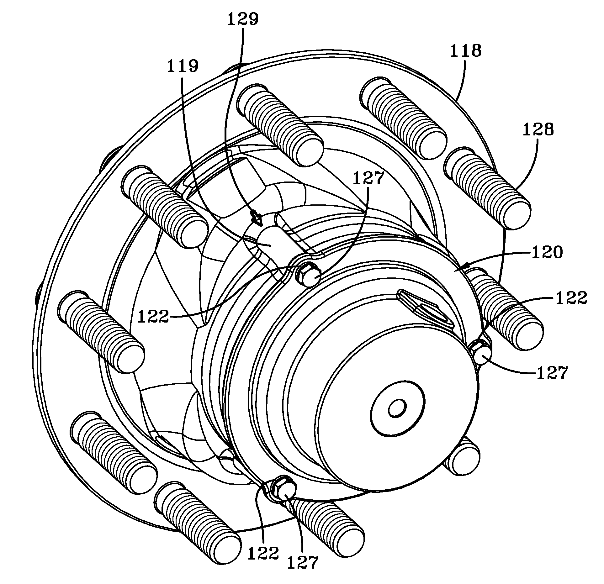
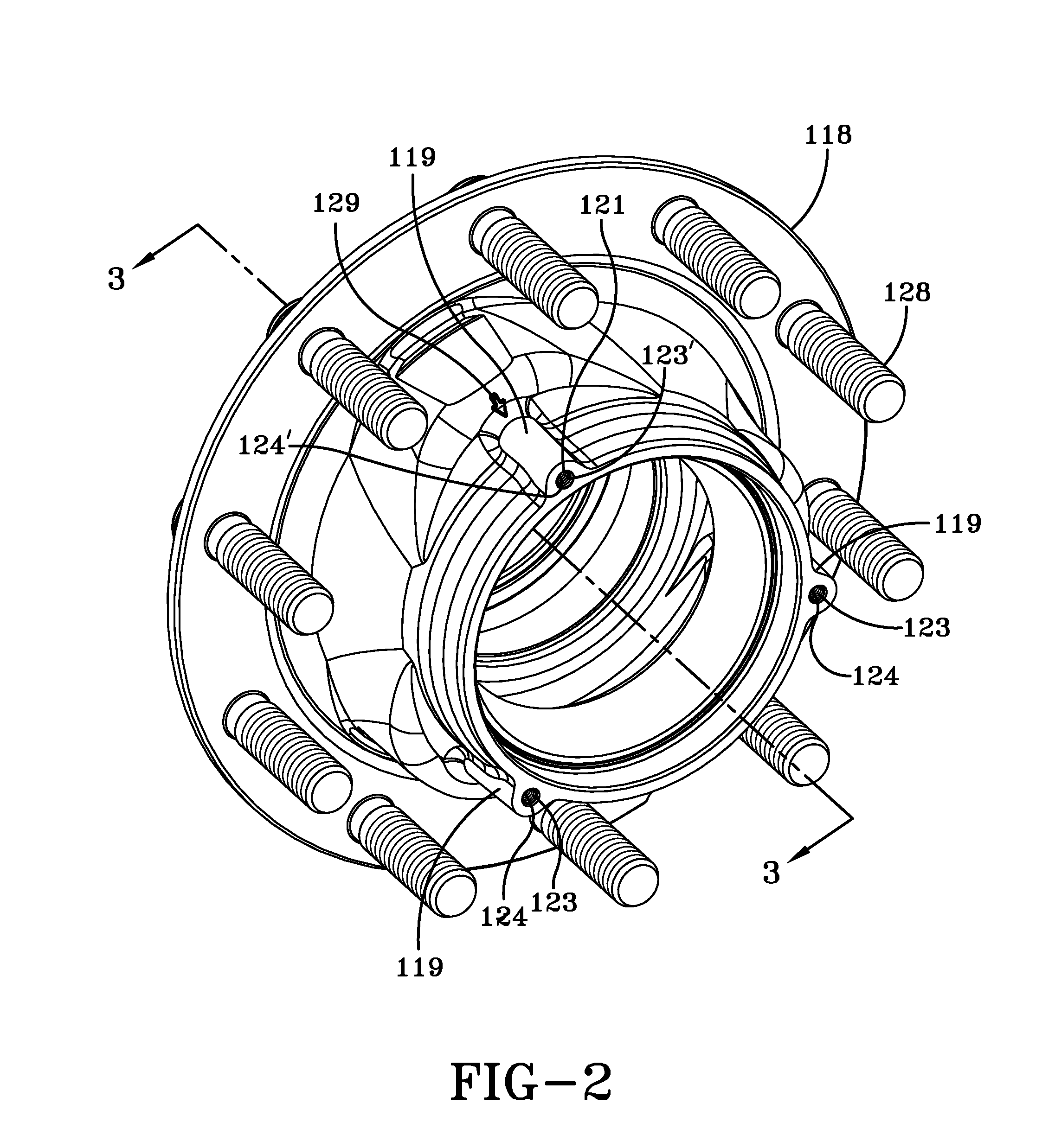
[0017]Yet another objective of the present invention is to provide a non-drive axle wheel hub that is capable of being filled with semi-fluid grease in a simple manner, and which is economical to manufacture.

Problems solved by technology

Therefore, the wheel end assembly must be sealed to prevent leakage of the lubricant, and also to prevent contaminants from entering the assembly, both of which could be detrimental to its performance.
Historically, oil has been used as the lubricant for the bearing assemblies, but it may not be the optimum lubricant for achieving the goal of increased bearing assembly life.
More particularly, if the main seal on the wheel hub assembly degrades, there is a tendency for the oil to leak out of the assembly due to its relatively low viscosity in comparison to other lubricants.
When the oil leaks out, the bearing assembly may become under-lubricated, which reduces its life.
Moreover, when the oil leaks out of the wheel end assembly, it may leak onto components of an associated brake system, such as the brake shoes, which must then be repaired, thereby increasing the cost associated with an oil leak.
Such potential disadvantages associated with oil leaks have led to increasing use of semi-fluid grease as a replacement for oil as a lubricant for bearing assemblies in wheel end assemblies on non-drive axles.
However, semi-fluid grease does not readily flow to both the inboard and outboard bearings and the hub area proximate the bearings using such a hubcap fill hole.
This method includes a distinct disadvantage, since the lack of the installation of the outer bearing during grease introduction requires that an operator maintain a relatively horizontal position of the wheel hub to prevent damaging the main seal of the wheel end assembly.
That is, without the outer bearing in place, there is a tendency for the outboard end of the wheel hub to drop down onto the axle spindle, which in turn can kink or damage the main seal at the inboard end of the wheel hub.
In addition, while this prior art method may be employed somewhat efficiently during initial assembly of the wheel end assembly with factory-trained assemblers, it is much less practical for use in the field, such as during servicing of the wheel end assembly, since the wheel end assembly would have to be at least partially disassembled just to add lubricant.
However, when high-strength, thin-wall wheel hub constructions are employed, a radially-oriented fill port formed in the wall of the wheel hub is not practical, since there may not be enough wall thickness in such a wheel hub to form adequate threads to secure a threaded plug.
In addition, the formation of the radially-oriented port involves an additional manufacturing operation, which undesirably increases the cost of the wheel hub.
However, if the drive stud is installed improperly, it may back out during service, in which case centrifugal force could force the lubricant out of the wheel hub, thereby potentially leading to damage of the bearings.
More importantly, this method cannot be used on wheel end assemblies for non-drive axles, since such wheel end assemblies lack the structure of drive-axle wheel hubs, and in particular, the outboard plate drive stud assembly, and associated holes formed in the wheel hub.
Thus, the above-described disadvantages of prior art methods for properly filling non-drive wheel hubs with semi-fluid grease, as well as the unacceptability of prior art methods employed to fill drive axle wheel hubs due to the differing structure of prior art non-drive axle wheel hubs, makes it desirable to develop a non-drive axle wheel hub that is capable of being filled with semi-fluid grease without manipulation of the outboard bearing or using a radially-oriented fill port, while being economical to manufacture.

Method used


Image

  • Wheel hub with lubricant fill port
  • Wheel hub with lubricant fill port
  • Wheel hub with lubricant fill port

Examples


Embodiment Construction

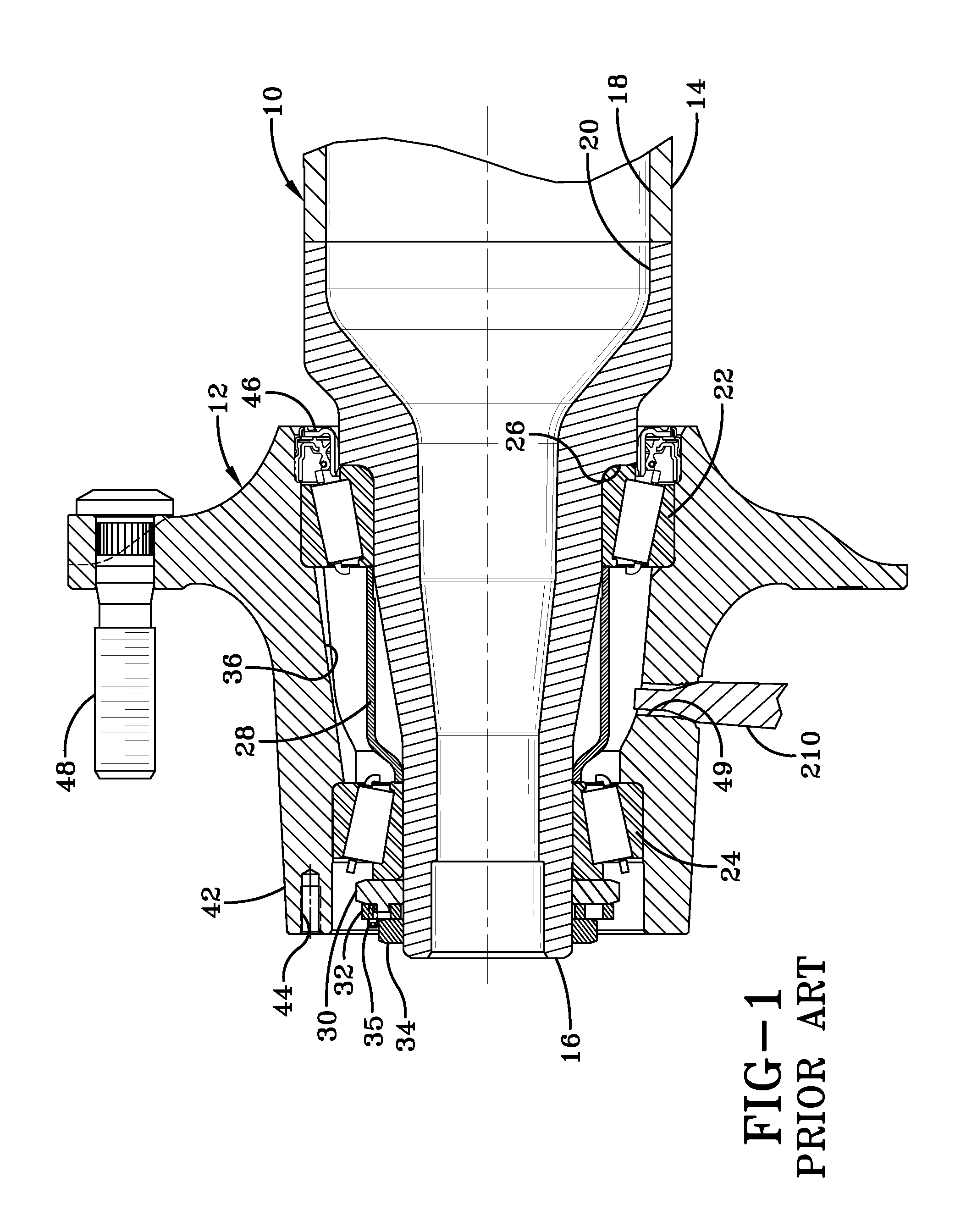
[0026]In order to better understand the wheel hub of the present invention, a prior art wheel hub is shown incorporated into an axle spindle and wheel end assembly for a heavy-duty vehicle in FIG. 1 and now will be described. Non-drive axle 10 depends from and extends transversely across the trailer of a heavy-duty tractor-trailer (not shown). A typical heavy-duty tractor-trailer includes one or more non-drive axles 10 suspended from the trailer, with each of the axles having a wheel end assembly 12 mounted on each end of the axle. For the sake of clarity, only one axle end and wheel end assembly 12 will be described herein. Axle 10 includes a central tube 14, and an axle spindle 16 is integrally connected by any suitable means, such as welding, to each end of the central tube. Axle central tube 14 generally is tubular-shaped and is formed with an internal cavity 18. Axle spindle 16 is tapered and is formed with a correspondingly tapered internal cavity 20.

[0027]Wheel end assembly 1...


PUM


Abstract

A non-drive axle depends from a heavy-duty vehicle. Each one of a pair of wheel end assemblies is mounted on a respective one of the ends of the non-drive axle. Each wheel end assembly includes a pair of bearings mounted on a spindle of the axle, and a wheel hub rotatably mounted on the bearings. A cavity is formed in the wheel end assembly between the bearings. A port is formed in the wheel hub and extends generally parallel to a central axis of the wheel hub, and communicates with the outboard surface of the wheel hub and the cavity. Lubricant for the bearings is introduced into the cavity by means of the port, and the port is tapped to receive a plug to seal it and contain the lubricant in the cavity. The port also receives a bolt that secures a hubcap to the wheel hub.

Description

CROSS-REFERENCE TO RELATED APPLICATION[0001]This application claims the benefit of U.S. Provisional Patent Application Ser. No. 60 / 833,684, which was filed on Jul. 27, 2006.BACKGROUND OF THE INVENTION[0002]1. Technical Field[0003]The invention relates to wheel end assemblies, and in particular to wheel end assemblies for non-drive axles of heavy-duty vehicles, such as tractor-trailers. More particularly, the invention is directed to a wheel hub of a heavy-duty wheel end assembly, in which the wheel hub includes a lubricant fill port that is formed in an existing hubcap bolt hole and which has an internal plug for ensuring containment of the lubricant within the wheel end assembly.[0004]2. Background Art[0005]For many years, the heavy-duty vehicle industry has utilized wheel end assemblies which typically are mounted on each end of one or more non-drive axles. Each wheel end assembly typically includes a hub rotatably mounted on a bearing assembly, which includes an inboard bearing a...

Claims


Application Information

Patent Timeline
Patent Type & Authority Applications(United States)
IPC IPC(8): B60B27/00F01M9/12
CPCB60B27/001F16C35/04F16C33/6622F16C19/386F16C33/581F16C35/042F16C2326/02
Inventor WHITE, JAY D.HESTER, LARRY B.MUTZNER, KENNETH D.WILCHECK, MICHAEL W.
Owner HENDRICKSON USA L L C
Learn More