Thin-Film Slicer
a thin film, slicer technology, applied in the direction of preparing samples for investigation, metal working apparatus, sawing apparatus, etc., can solve the problems of time and labor, not designed for thin film cutting, and high cost of standard slicers, and achieve the effect of easy-to-make thin-film slices
- Summary
- Abstract
- Description
- Claims
- Application Information
AI Technical Summary
Benefits of technology
Problems solved by technology
Method used
Image
Examples
first embodiment
(Vertical Slicer)
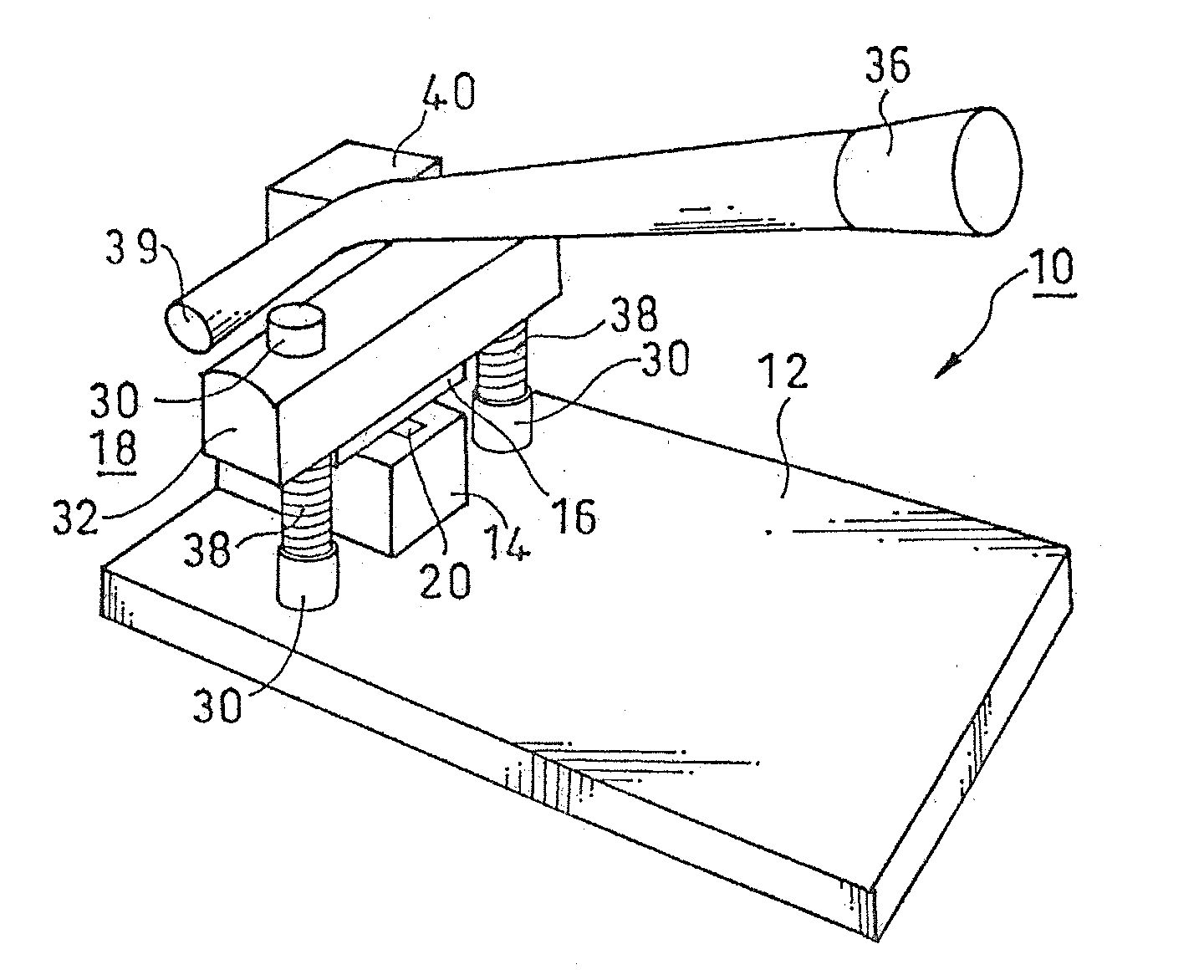
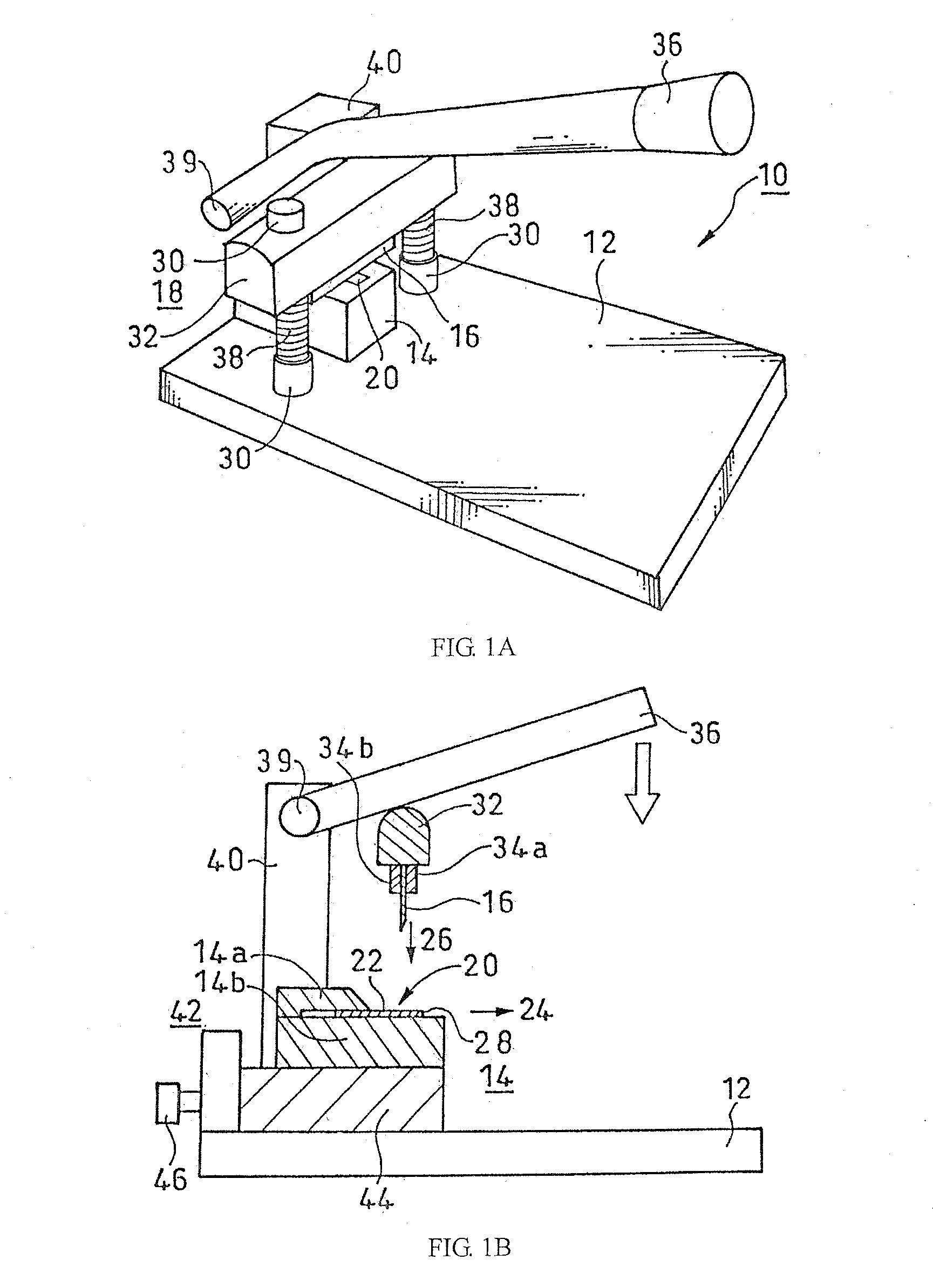
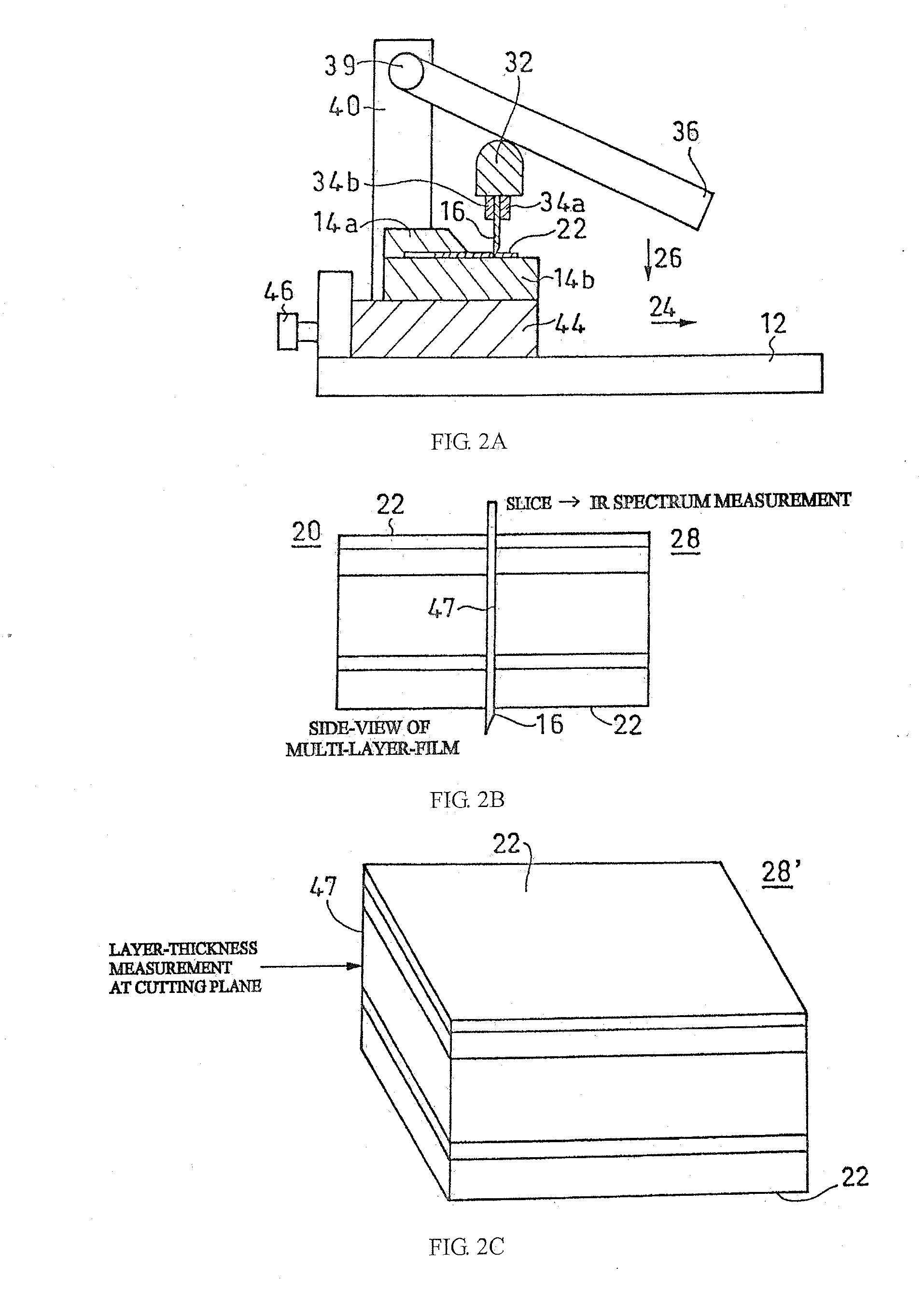
[0043] In the present invention, it is preferred that a vertical slicer be used for making a suitable surface of film having, for example, a thickness of about 30 μm to 1 mm and for making a thin-film slice having, for example, a thickness of about 30 μm to 1 mm. Since the vertical slicer cuts the thin film perpendicularly to its sample surfaces, it is suited to layer-thickness measurement at a cutting plane 47. An obtained slice can be disc-molded with the use of a KBr plate or a mini-plate for layer identification by infrared transmission microscopy. A suitable film thickness for cutting is about 30 μm to 650 μm.
[0044]FIGS. 1A and 1B show an outline stricture of a vertical slicer according to an embodiment of the present invention. FIG. 1A is an outline perspective view of the vertical slicer according to the present embodiment, and FIG. 1B is an equivalent view showing a vertical cross-section of a main part thereof.
[0045] In the present embodiment, the sampl...
third embodiment
(Cutting-Blade Arrangement)
[0095] When a sample is highly elastic, like soft rubber, and soft, the sample may be likely to distort during cutting.
[0096] To increase the machinability of a tilted slicer, the present embodiment pays special attention to the direction of the tip of a cutting blade.
[0097] When a tilted slicer is viewed from the top as shown in FIG. 5, the cutting blade 116 is placed such that the end-edge direction 162 of the tip of the cutting blade 116 is directed in a direction 164 which is at an angle with respect to the direction perpendicular to the feeding direction 126 of the cutting blade 116 in a horizontal plane 160 drawn by the tip of the cutting blade 116.
[0098] Therefore, in the present embodiment, when the cutting blade 116 is horizontally fed toward the sample surfaces 122 of the thin-film 120, the cutting blade 116 first cuts an end of the sample surfaces 122 of the thin film 120, and then, cuts toward the other end in the width direction.
[0099] I...
fourth embodiment
(Supersonic Vibration of Cutting Blade)
[0100] When the cutting blade 116 is manually fed, the manual-feeding speed determines the cutting speed. If a block of fish or meat is the sample, even when the cutting blade is moved up and down at a usual speed, a certain degree of machinability is obtained. However, if a thin film is cut, higher machinability is required compared with a case in which a block of fish or meat is cut.
[0101] It is preferred in the present invention that supersonic vibration be applied to the tip of the cutting blade 116 in the cutting direction, in addition to manual feeding. With this, the present invention greatly increases the cutting speed when the thin film 120 is cut. The cutting quality depends on the feeding speed of the cutting blade 116, and increases as the cutting speed increases. Since friction between the cutting blade 116 and the thin film 120 is largely reduced in the present invention, it is considered that this factor also contributes to im...
PUM
| Property | Measurement | Unit |
|---|---|---|
| thickness | aaaaa | aaaaa |
| thickness | aaaaa | aaaaa |
| angle | aaaaa | aaaaa |
Abstract
Description
Claims
Application Information
 - R&D
- Intellectual Property
- Life Sciences
- Materials
- Tech Scout
- Unparalleled Data Quality
- Higher Quality Content
- 60% Fewer Hallucinations
Browse by: Latest US Patents, China's latest patents, Technical Efficacy Thesaurus, Application Domain, Technology Topic, Popular Technical Reports.
© 2025 PatSnap. All rights reserved.Legal|Privacy policy|Modern Slavery Act Transparency Statement|Sitemap|About US| Contact US: help@patsnap.com


