Scanner

a scanner and scanning technology, applied in the field of scanners, can solve the problems of deteriorating resolution, not embodied in high resolution, and unable to perform more complicated operations of scanners, and achieve the effect of eliminating tremors and high definition image quality

Inactive Publication Date: 2008-01-24
SAMSUNG ELECTRONICS CO LTD
View PDF9 Cites 8 Cited by
  • Summary
  • Abstract
  • Description
  • Claims
  • Application Information

AI Technical Summary

Benefits of technology

[0021]The present invention provides a scanner which can embody a high definition image quality by eliminating a tremor caused by a high frequency.
[0022]The present invention also provides a scanner which does not need an electrical control and an additional part, and also is highly favorable to manufacturing and does not incur an additional cost by providing a low pass filter having a mechanical structure with only a comparatively simple change of a mechanical design.
[0023]The present invention also provides a scanner which can precisely control a location by effectively eliminating an intervention of a high frequency, and when applied to a scanner, can also prevent a resolution from being deteriorated, which may be caused by overlapping scanning lines, by constantly maintaining a vertical isolation distance between scanning lines.
[0024]The present invention also provides a scanner which has a small dynamic deformation, while having a relatively large mirror and a relatively large driving angle, by providing a rib in a rear of a mirror, an external gimbal, an internal gimbal, and a torsion spring, and thereby may embody a high definition image quality.

Problems solved by technology

In addition, the scanner may perform more complicated operations such as complex image processing, e.g., for a laser television or the like.
Such a tremor may prevent a scanning line from being scanned to a desired location and thus, deteriorate a resolution.
Specifically, in the case of vertical scanning, horizontal scanning lines may be overlapped due to a tremor caused by a high frequency, and thus, may not embody a high resolution.
Specifically, scanning lines may be overlapped with each other or excessively separated from each other.
As described above, intervals between horizontal scanning lines may be irregular which may significantly deteriorate a resolution.
However, since electric parts may be required, productivity may be deteriorated and a manufacturing cost may be increased.
However, as the mirror moves at a higher speed and the diameter of the mirror becomes larger, a dynamic deformation becomes larger.
However, the related art mirror structure may not satisfy this requirement.
However, a high moment of inertia may cause an increase of rigidity of the mirror, and the driving angle of the mirror with respect to an identical torque becomes smaller.
Accordingly, a high moment of inertia is not a suitable solution.

Method used


Image

  • Scanner
  • Scanner
  • Scanner

Examples


Embodiment Construction

[0040]Reference will now be made in detail to exemplary embodiments of the present invention, examples of which are illustrated in the accompanying drawings, wherein like reference numerals refer to the like elements throughout. The exemplary embodiments are described below in order to explain the present invention by referring to the figures.

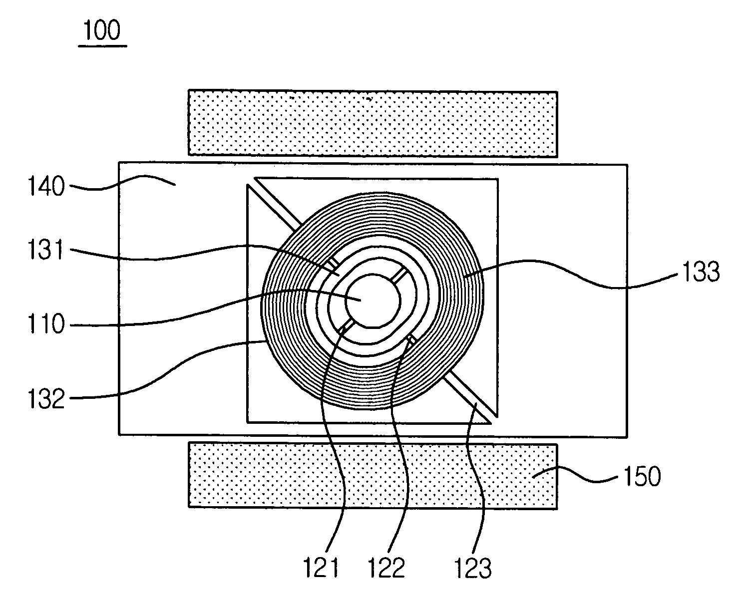
[0041]FIG. 3 is a perspective view illustrating a scanner according to an exemplary embodiment of the present invention.

[0042]As shown in FIG. 3, the scanner 100 according to an exemplary embodiment of the present invention includes a mirror 110. The mirror 110 reflecting a light source is provided on a center of the scanner, and an internal gimbal 131 is provided around the mirror 110. The internal gimbal 131 is approximately in a shape of an oval. However, other shapes are also contemplated. For example, the shape may be circular or polygonal. In the exemplary embodiment shown in FIG. 3, a shape of the oval is not a perfect circle, and simila...


PUM


Abstract

A scanner for removing a high frequency component from an external input using a mechanical structure of the scanner is provided. The scanner includes a mirror; an internal gimbal which is provided around the mirror; an external gimbal which is provided around the internal gimbal, including a driving coil; a frame which is provided around the external gimbal; a first torsion axis which connects the mirror and the internal gimbal; a connection axis which connects the internal gimbal and the external gimbal, and is perpendicular to the first torsion axis; a second torsion axis which connects the external gimbal and the frame, and is parallel to the connection axis; and a magnet which forms a magnetic field having an angle with a direction of the second torsion axis, wherein a high frequency vibration is filtered through the connection axis and transferred to the mirror.

Description

CROSS-REFERENCE TO RELATED APPLICATION[0001]This application claims priority from Korean Patent Application No. 10-2006-0066702, filed on Jul. 18, 2006, in the Korean Intellectual Property Office, the disclosure of which is incorporated herein in its entirety by reference.BACKGROUND OF THE INVENTION[0002]1. Field of the Invention[0003]Apparatuses consistent with the present invention relate to a scanner, and more particularly, to a scanner which can remove a particular high frequency component from an external input by providing a low pass filter with only a comparatively simple change of a mechanical design, and also can eliminate a tremor caused by a high frequency.[0004]2. Description of Related Art[0005]A scanner is usually used to change a path of a laser. Such a scanner may further be easily used for a laser printer, a bar code reader, and the like. In addition, the scanner may perform more complicated operations such as complex image processing, e.g., for a laser television o...

Claims


Application Information

Patent Timeline
IPC IPC(8): G02B26/08
CPCG02B26/101G02B26/085B81B7/02G02B26/105H04N1/113
Inventor CHO, JIN WOOJEONG, HEE MOONKO, YOUNG CHULSHIN, SEONG HOLEE, JIN HO
Owner SAMSUNG ELECTRONICS CO LTD
Why Eureka
Try Eureka