Objective optical system for endoscope
An optical system and a technology for endoscopes, which are applied to the field of objective lens optical systems for endoscopes, can solve problems such as vignetting at the periphery of a picture, and achieve the effects of reducing optical performance, high definition, and suppressing focus shift.
- Summary
- Abstract
- Description
- Claims
- Application Information
AI Technical Summary
Problems solved by technology
Method used
Image
Examples
Embodiment 1
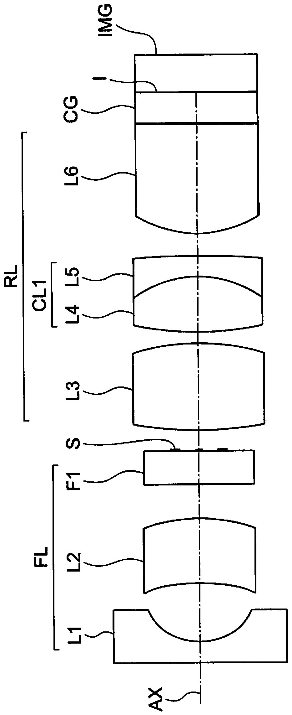
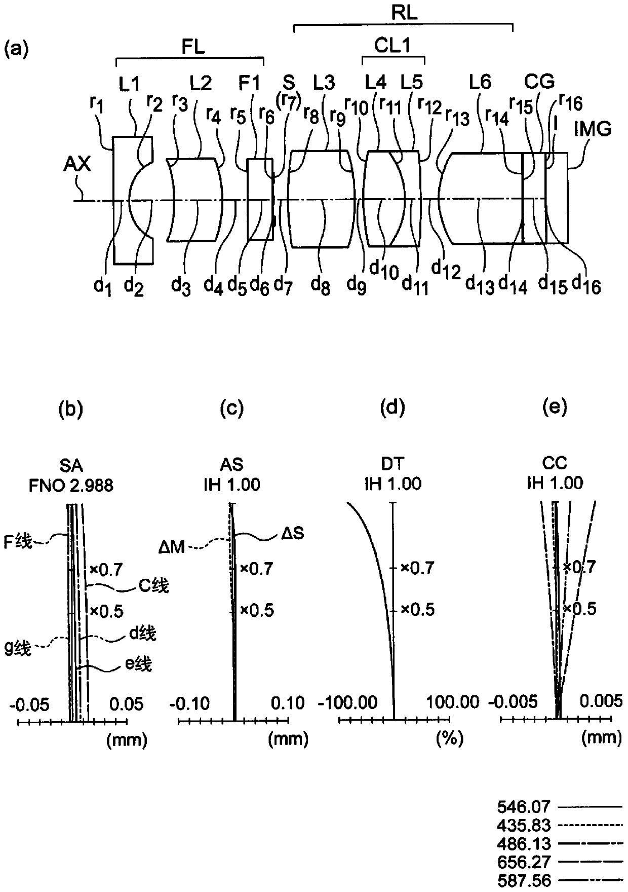
[0178] The objective optical system for an endoscope according to Example 1 will be described. figure 2 (a) is a figure which shows the lens cross-sectional structure of the objective optical system for endoscopes concerning this Example.
[0179] The present embodiment is composed of a front group FL of negative overall refractive power, an aperture stop S, and a rear group RL of generally positive refractive power arranged in this order from the object side.
[0180] In this embodiment, a first lens L1 having a plano-concave shape with a flat object side and a negative refractive power, and a second lens L1 having a meniscus shape with a convex surface facing the image side and a positive refractive power are arranged in order from the object side. Lens L2, infrared cut filter F1 of parallel plate, aperture stop S, third lens L3 with biconvex shape and positive refractive power, fourth lens L4 with biconvex shape and positive refractive power and convex surface The cemente...
Embodiment 2
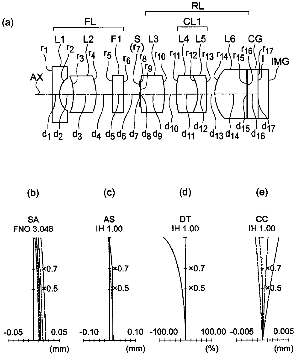
[0187] The objective optical system for an endoscope according to Example 2 will be described. image 3 (a) is a figure which shows the lens cross-sectional structure of the objective optical system for endoscopes concerning this Example.
[0188] The present embodiment is composed of a front group FL of negative overall refractive power, an aperture stop S, and a rear group RL of generally positive refractive power arranged in this order from the object side.
[0189] In this embodiment, a first lens L1 having a plano-concave shape with a flat object side and a negative refractive power, and a second lens L1 having a meniscus shape with a convex surface facing the image side and a positive refractive power are arranged in order from the object side. Lens L2, infrared cut filter F1 of parallel plate, aperture stop S, third lens L3 with biconvex shape and positive refractive power, fourth lens L4 with biconvex shape and positive refractive power and convex surface The cemented...
Embodiment 3
[0194] The objective optical system for an endoscope according to Example 3 will be described. Figure 4 (a) is a figure which shows the lens cross-sectional structure of the objective optical system for endoscopes concerning this Example.
[0195] The present embodiment is composed of a front group FL of negative overall refractive power, an aperture stop S, and a rear group RL of generally positive refractive power arranged in this order from the object side.
[0196] In this embodiment, a first lens L1 having a plano-concave shape with a flat object side and a negative refractive power, and a second lens L1 having a meniscus shape with a convex surface facing the image side and a positive refractive power are arranged in order from the object side. Lens L2, an infrared cut filter F1 of a parallel plate, an aperture stop S, a third lens L3 having a biconvex shape and a positive refractive power, a fourth lens L4 having a biconvex shape and a positive refractive power, and a ...
PUM
 Abstract
Description
Claims
Application Information
 - R&D
- Intellectual Property
- Life Sciences
- Materials
- Tech Scout
- Unparalleled Data Quality
- Higher Quality Content
- 60% Fewer Hallucinations
Browse by: Latest US Patents, China's latest patents, Technical Efficacy Thesaurus, Application Domain, Technology Topic, Popular Technical Reports.
© 2025 PatSnap. All rights reserved.Legal|Privacy policy|Modern Slavery Act Transparency Statement|Sitemap|About US| Contact US: help@patsnap.com


