
Method and system for assisting the driver of a motor vehicle in identifying road bumps

a technology for motor vehicles and road bumps, applied in vehicle position/course/altitude control, process and machine control, instruments, etc., can solve problems such as excessive speed, driver failure to notice road bumps, and driver driving over them at an excessive speed, so as to achieve the effect of reducing or eliminating the problem

Inactive Publication Date: 2008-01-17
ROBERT BOSCH GMBH
View PDF7 Cites 55 Cited by
  • Summary
  • Abstract
  • Description
  • Claims
  • Application Information

AI Technical Summary

Benefits of technology

[0007] An object of the present invention is to provide an improved method, i.e., driver assistance system of the above-mentioned type, which would strongly support the driver in detecting obstacles for the vehicle and minimize or even completely prevent the risk of driving over road bumps at an excessive speed and the resulting consequences.

Problems solved by technology

Possible obstacles for a vehicle also include road bumps built into the road intentionally as speed bumps to force the driver to reduce the driving speed.
Yet it may happen that the driver fails to notice a road bump, in particular in complex driving situations.
Especially when trying to find his way in strange cities and due to general distraction sources such as fellow passengers or in the event of tiredness, there is the danger that a road bump is not noticed in a timely manner or at all and the driver drives over it at an excessive speed.
Also, at night or under poor visibility conditions, there is an increased risk that a road bump is not recognized by the driver, especially if color markings such as white zig-zag lines fade over time and are unable to adequately fulfill their desired warning function.
In addition to the strong vibrations caused thereby to the vehicle and the passengers, chassis components may also be damaged.
More importantly, the service life of the shock absorbers is considerably reduced.
Since, if the vehicle is driven over a road bump at an unadjusted speed, it partially loses contact with the ground, the braking distance of an initiated or ongoing braking maneuver becomes longer.
In the worst case, the vehicle may become fully uncontrollable.
This short braking pressure results in the driver himself starting to brake after a very short delay.
However, the forward-looking range, a maximum of 5 m, is relatively limited, so that in many cases the driver is no longer able to react to the warning in a timely manner.

Method used


Image

  • Method and system for assisting the driver of a motor vehicle in identifying road bumps
  • Method and system for assisting the driver of a motor vehicle in identifying road bumps

Examples


Embodiment Construction

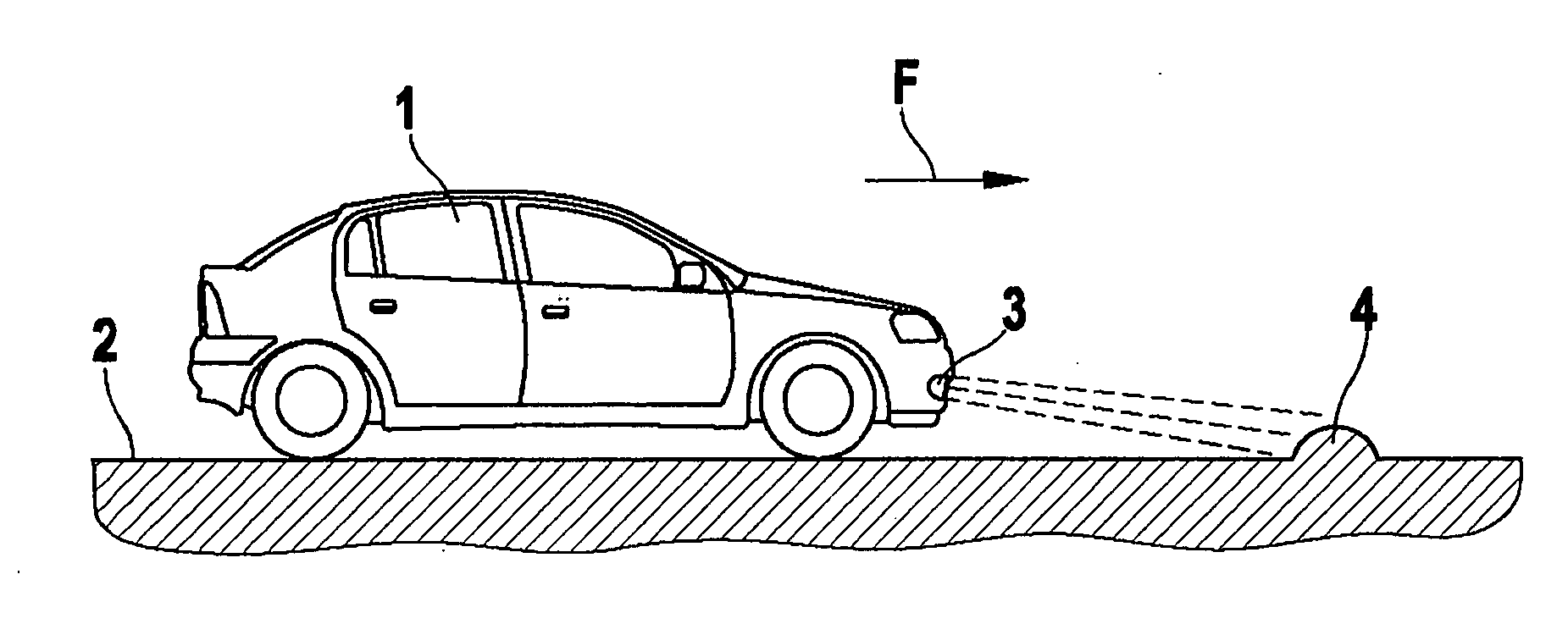
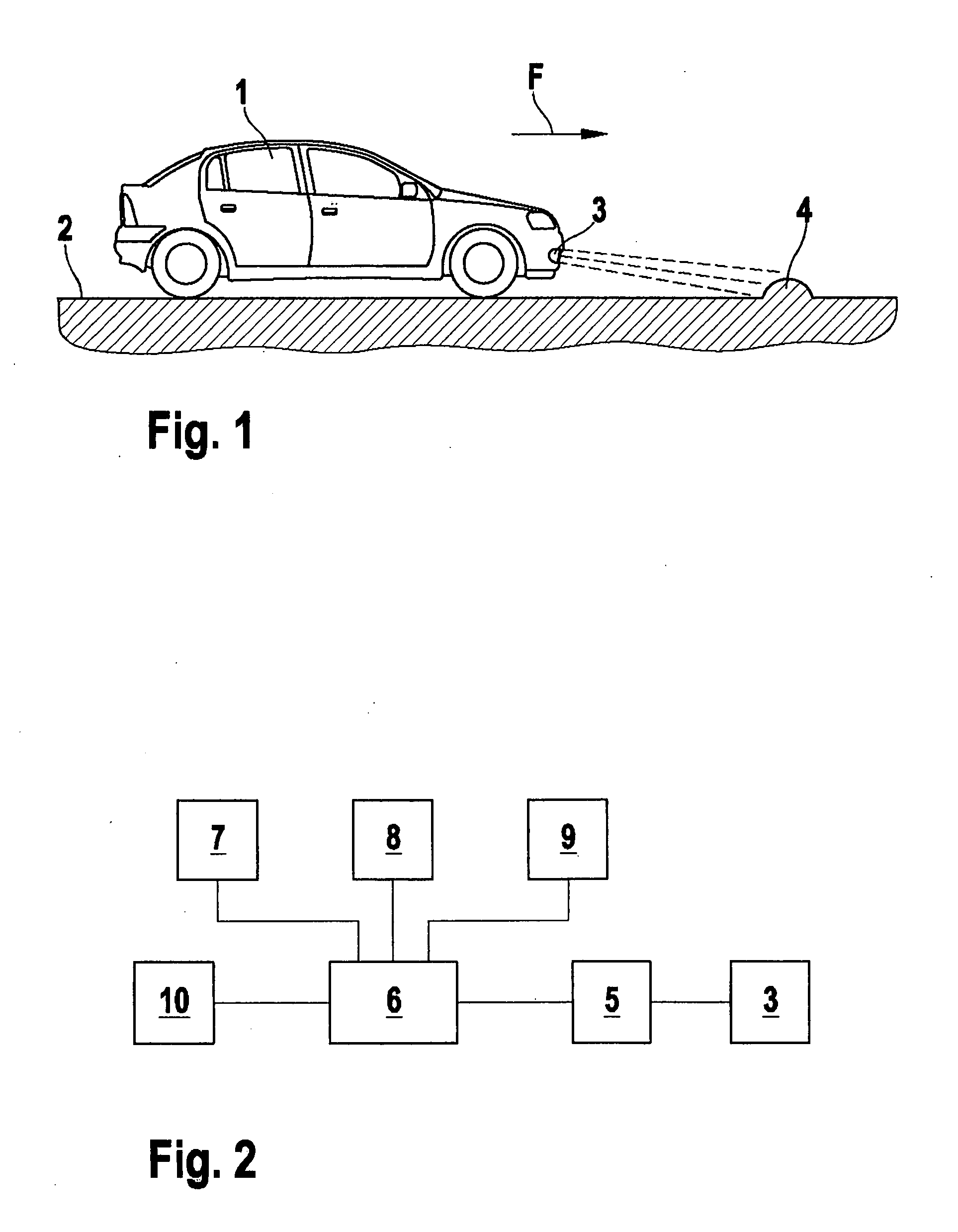
[0032] The example method according to the present invention and the example system according to the present invention are used in particular in motor vehicles. FIG. 1 shows a motor vehicle 1, which moves on a road 2 in a driving direction F illustrated by an arrow. In the front area of motor vehicle 1, a sensor 3 is situated for detecting objects in front of motor vehicle 1 on road 2. Sensor 3 is a video sensor in this case. Sensor 3 detects road bumps 4, which are intentionally built into road 2 for speed reduction (FIG. 1).

[0033] The data detected by sensor 3 are supplied to an evaluation unit 5, which ascertains, at least with a high probability, whether or not the object detected by sensor 3 is a road bump 4 using optical image processing algorithms.

[0034] Evaluation unit 5 is connected to a control unit 6, which activates a visual 7 and / or acoustic 8 and / or haptic 9 warning signal generating means as a function of the result ascertained by evaluation unit 5, when a detected ...


PUM


Abstract

A system and method for assisting the driver of a vehicle in identifying obstacles for the vehicle as is described. Objects located outside the vehicle are detected with the aid of object detector. If objects are detected, information is given to the driver and / or to defined components of the vehicle. An evaluation unit ascertains whether a detected object is a road bump, and information is given to the driver and / or to components of the vehicle only if a detected object is a road bump.

Description

FIELD OF THE INVENTION [0001] The present invention relates to a method for assisting the driver of a vehicle in identifying obstacles for the vehicle, objects located outside the vehicle being detected with the aid of object detection means and, if objects are detected, information is given to the driver and / or to defined components of the vehicle. BACKGROUND INFORMATION [0002] Methods of this type are known within driver assistance systems in motor vehicles. They are to assist the driver in driving the vehicle by pointing out possible obstacles for the vehicle in addition to his own perception and in particular warning him of imminent dangers or collisions. [0003] German Patent Application No. DE 103 59 413 A1 describes a system and a method for collision warning in motor vehicles in which objects located outside the vehicle are detected and displayed in a display unit. [0004] Possible obstacles for a vehicle also include road bumps built into the road intentionally as speed bumps...

Claims


Application Information

Patent Timeline
IPC IPC(8): G06F17/00B60W30/16
CPCB60T7/22B60W30/16G08G1/16G01S7/41G08G1/0967B60W30/17G08G1/165
Inventor HAUG, KARSTEN
Owner ROBERT BOSCH GMBH
Learn More