
Method for Making a Pillar-Type Phase Change Memory Element

Active Publication Date: 2008-01-17
MACRONIX INT CO LTD
View PDF99 Cites 165 Cited by
  • Summary
  • Abstract
  • Description
  • Claims
  • Application Information

AI Technical Summary

Benefits of technology

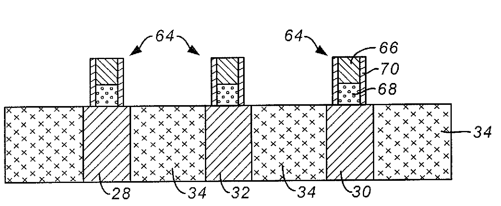
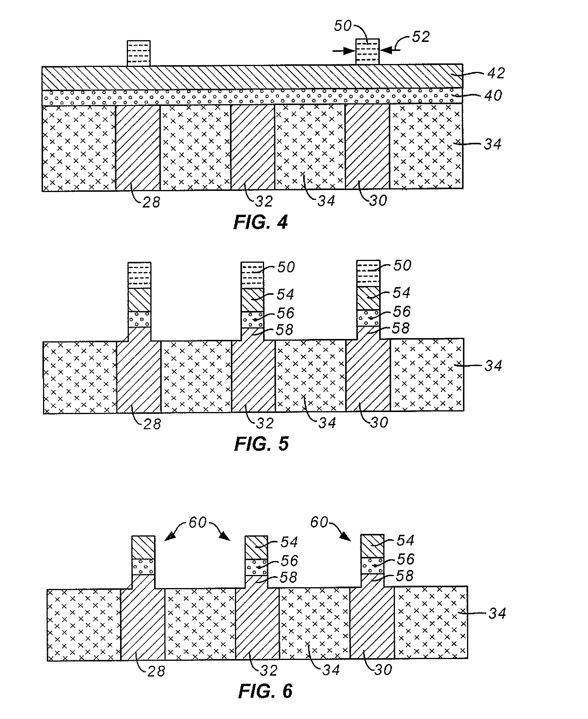
[0012]A second aspect of the invention is directed to method for making a pillar-type phase change memory element comprising first and second electrode elements and a phase change element therebetween. First and second electrode materials are selected. A chlorine-sensitive phase change material is selected. A first electrode element, the first electrode element comprising the first electrode material, is formed. The phase change material is deposited on the first electrode element and the second electrode material is deposited on the phase change material. An etching mask is formed over the second electrode material and trimmed. A first etching procedure that does not use a chlorine gas is selected. The second electrode material and the phase change material not masked by the trimmed mask are etched according to the first etching procedure to form a preliminary second electrode element and a preliminary phase change element respectively while redepositing at least one of the first and second electrode materials onto the preliminary phase change element to create a preliminary pillar-type phase change memory element. A second etching procedure that does not use a chlorine gas is selected. The preliminary pillar-type phase change memory element is etched according to the second etching procedure to remove the redeposited etched material thus forming a second electrode element and a phase change element thereby creating a pillar-type phase change memory element. The method is carried out so that the phase change element is not undercut relative to the second electrode element during the preliminary pillar-type phase change memory element etching step.

Problems solved by technology

Problems have arisen in manufacturing such devices with very small dimensions, and with variations in process that meet tight specifications needed for large-scale memory devices.

Method used


Image

  • Method for Making a Pillar-Type Phase Change Memory Element
  • Method for Making a Pillar-Type Phase Change Memory Element
  • Method for Making a Pillar-Type Phase Change Memory Element

Examples


Embodiment Construction

[0024]The following description of the invention will typically be with reference to specific structural embodiments and methods. It is to be understood that there is no intention to limit the invention to the specifically disclosed embodiments and methods but that the invention may be practiced using other features, elements, methods and embodiments. Like elements in various embodiments are commonly referred to with like reference numerals.

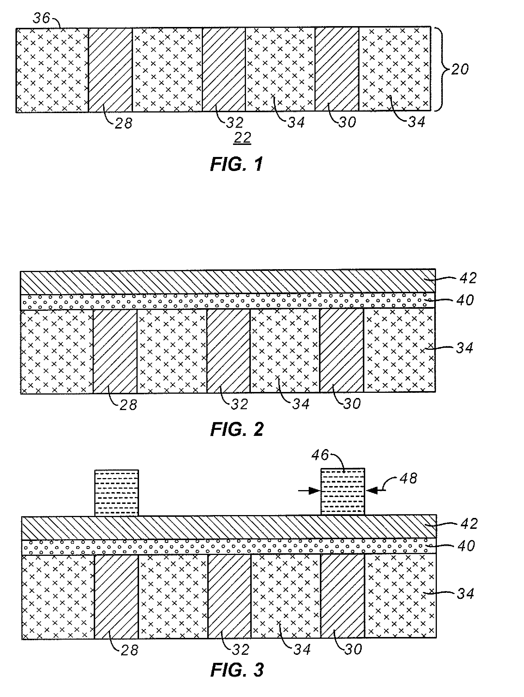
[0025]Methods for making pillar-type a phase change memory elements will be described with reference to FIGS. 1-7. Referring now to FIG. 1, a memory cell access layer 20 is shown formed on a substrate 22. Access layer 20 typically comprises access transistors (not shown); other types of access devices may also be used. Access layer 20 comprises first, second and third plugs 28, 30 and 32 all within a dielectric film layer 34. First, second and third plugs 28, 30 and 32, which will act as first electrode elements, are typically made of tungsten, p...


PUM


Abstract

A pillar-type phase change memory element comprises first and second electrode elements and a phase change element therebetween. A second electrode material and a chlorine-sensitive phase change material are selected. A first electrode element is formed. The phase change material is deposited on the first electrode element and the second electrode material is deposited on the phase change material. The second electrode material and the phase change material are etched without the use of chlorine to form a second electrode element and a phase change element. The second electrode material selecting step, the phase change material selecting step and the etching procedure selecting step are carried out so that the phase change element is not undercut relative to the second electrode element during etching.

Description

PARTIES TO A JOINT RESEARCH AGREEMENT[0001]International Business Machines Corporation, a New York corporation; Macronix International Corporation, Ltd., a Taiwan corporation, and Infineon Technologies A.G., a German corporation, are parties to a Joint Research Agreement.BACKGROUND OF THE INVENTION[0002]1. Field of the Invention[0003]The present invention relates to high density memory devices based on memory materials, in particular phase change based memory materials, including chalcogenide based materials and other materials, and to methods for manufacturing such devices.[0004]2. Description of Related Art[0005]Phase change based memory materials are widely used in read-write optical disks. These materials have at least two solid phases, including for example a generally amorphous solid phase and a generally crystalline solid phase. Laser pulses are used in read-write optical disks to switch between phases and to read the optical properties of the material after the phase change....

Claims


Application Information

Patent Timeline
IPC IPC(8): H01L21/00
CPCH01L45/06H01L45/1675H01L45/144H01L45/1233H10N70/231H10N70/8828H10N70/063H10N70/826
Inventor LUNG, HSIANG-LANHO, CHIAHUA
Owner MACRONIX INT CO LTD
Learn More