Any difference in either one of these, say 49 ohms versus 50 ohms, will cause the line to become unbalanced.
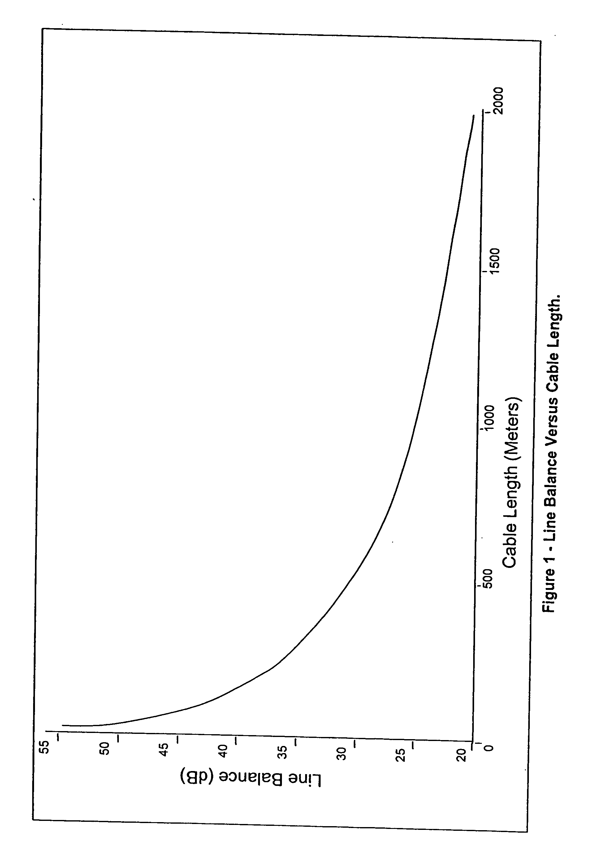
However, line unbalance builds up as the line lengthens, so a longer line will, under normal circumstances, be less balanced than a short line.
Such imbalance could lead to severe
crosstalk and susceptibility to both external electrical noise and to
radiation from the wire pair.
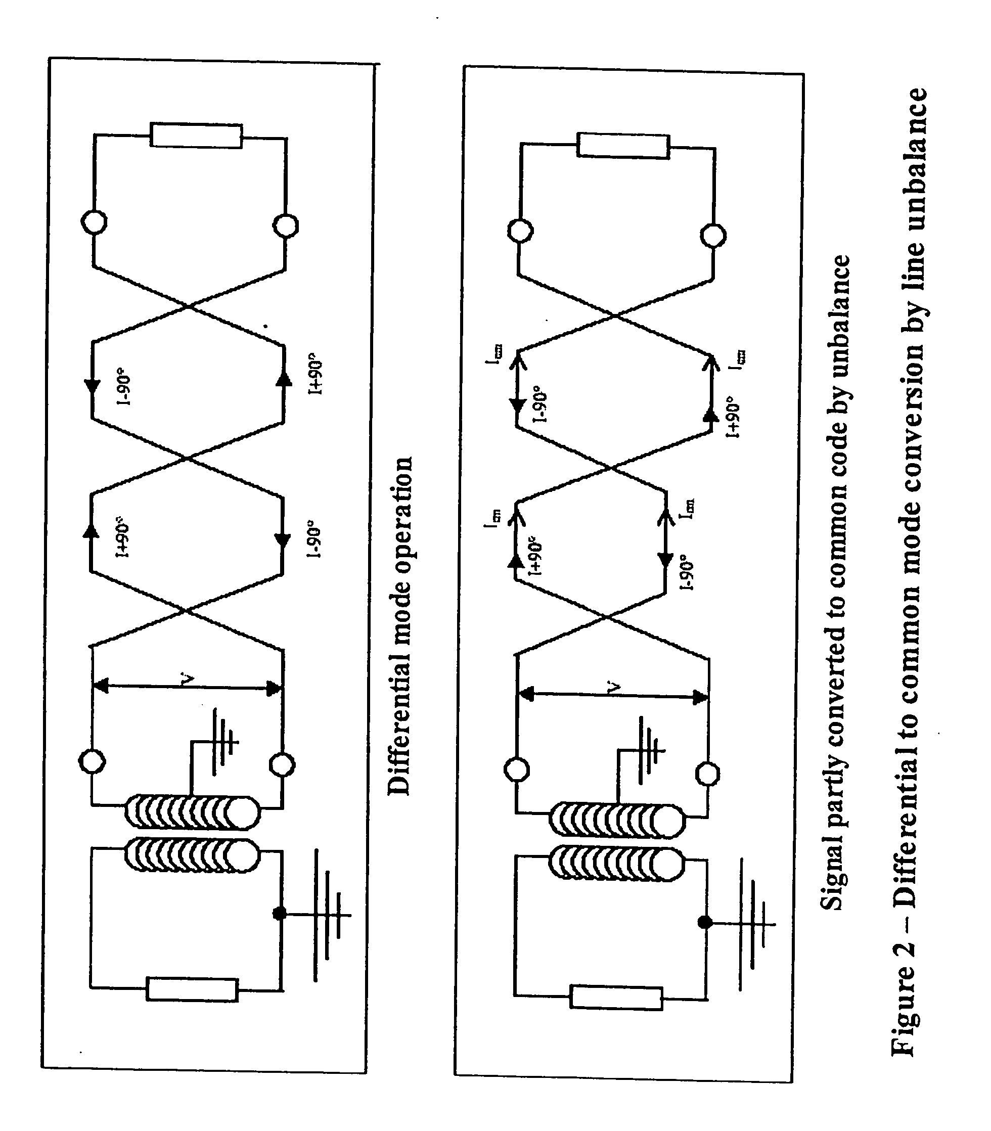
However, as shown on the lower drawing, any line unbalance will generate common mode signals that will be applied equally to the load.
A further problem stems from the method used to protect connected equipment from
high voltage events on the line.
Telephone lines are susceptible to external electromagnetic influences.
However, one of the worst interferers is “mains
hum”.
Line unbalance will convert part of this to a mains frequency differential
signal on the line.
This will have the effect of severely interfering with the operation of connected equipment.
Thus, an
unbalanced line will convert part of this to differential mode interfering noise.
This level of line unbalance will occur if, for example, the impedance of one wire is 51Ω and the impedance of the other is 48Ω.
This will be enough to cause severe
distortion of any wanted signals on the line.
Higher voltages and worse line balance will simply exacerbate this effect.
Also, the differential mains
hum engendered by line unbalance may reach voltages high enough to begin to saturate the transformers customarily used to protect the connected equipment from common mode voltages on the line.
All these effects obviously have a negative
impact on connected equipment and on the signals passing on the line.
Other forms of interference may be at frequencies or voltages that will directly affect the connected equipment.
Since this interference may, after conversion from common mode to differential mode by line unbalance, actually appear at frequencies used by the connected equipment, its presence in the line is directly destructive to the wanted signals.
However, these devices have not been adopted generally or even in specialized circumstances due to their minimal affect with regard to
noise reduction.
Where the incident signal
waves and the reflected signal
waves come together, standing
waves will result as the incident, and
reflected waves combine both constructively and destructively.
However, since common mode signals attenuate relatively slowly with increasing distance, standing waves may form over a large portion of the cable.
The actual impedance to ground experienced by a
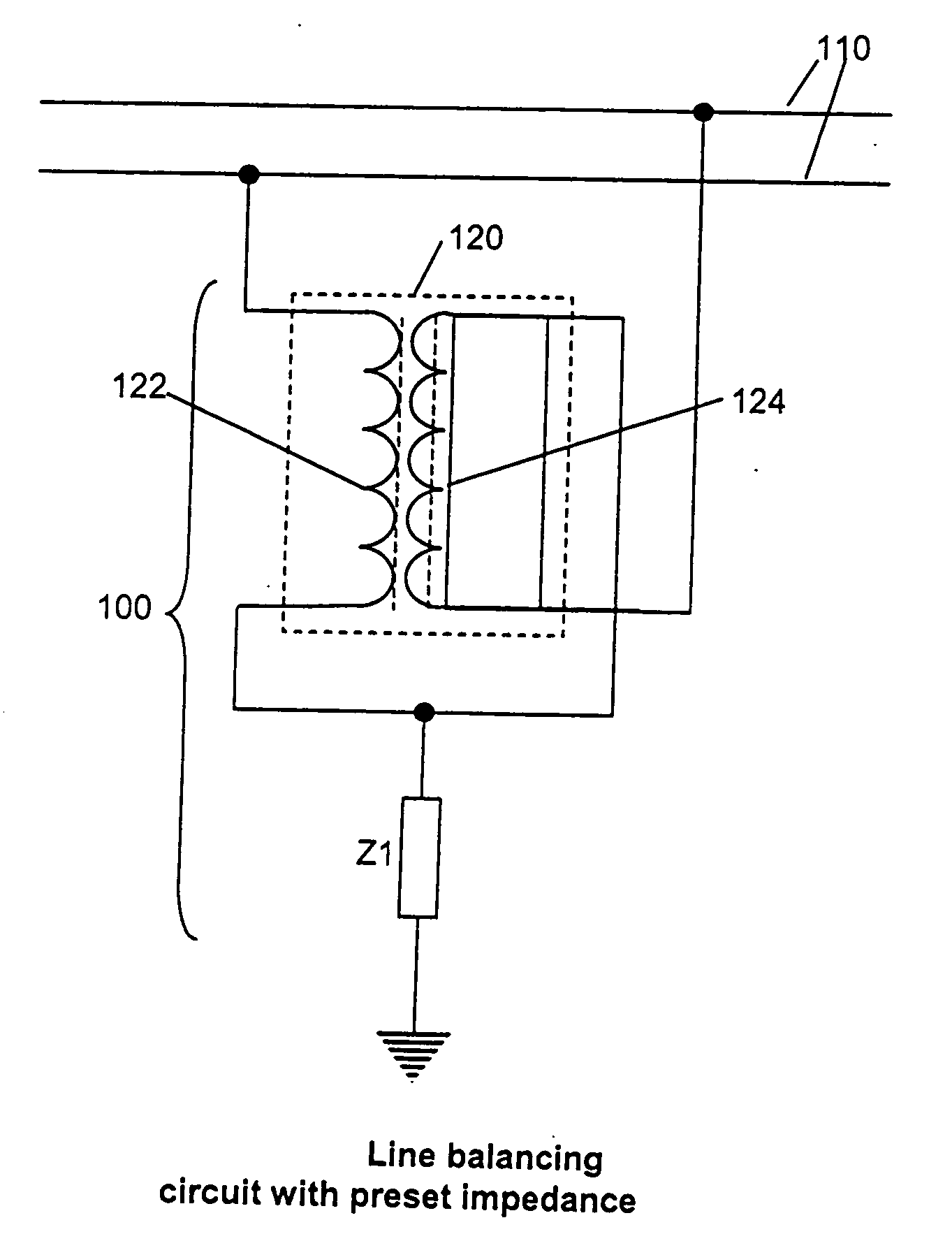
common mode signal encountering circuits constructed according to the invention will be very low, leading to common mode impedance mismatch.
However, the lower the impedance to ground, the greater the achieved line balance.
In addition to the noise sources described above, the phenomenon of
impulse noise exists within the premises to which the line is connected.
It was generally ignored because there was little that could be done to prevent the lightening storms, electric motors and electromechanical relays that caused the impulses.
While inaudible, these noise spikes can wreak havoc on data services, causing the IP
cyclic redundancy check that requests resends of errored packets of data to operate continuously and even causing the loss of packets entirely.
For
internet users, high amounts of
impulse noise cause the service to slow down significantly and can cause actual errors in downloaded data.
With
IPTV service, even low amounts of impulse noise result in video
pixelation or breaks in the audio content.
Line unbalance, caused by the nature of the wiring in the central office, is also worst at or close to the modem or DSLAM.
The result of this is that conversion of differential signals to
common mode noise is prevalent at or close to the central office or remote terminal (used to extend DSL signals to customers who would otherwise be out of reach) and a large portion of
crosstalk is generated close to the DSLAM.
Line unbalance is caused by a difference in impedance between the two wires of the line.
The impedance mismatch between individual wires of the pair results in a difference of signal amplitude between the wires, the level of amplitude mismatch being directly proportional to the impedance mismatch.
Reduction of
return loss will increase the reflection back into the line which leads to standing waves forming in the line.
However, in the real world,
transformer behaviour is limited by physical constraints.
One of those constraints is that any reasonably priced
transformer used at DSL frequencies will not operate correctly at voice frequencies.
This
voltage will propagate through the line, converting to
differential mode noise due to line unbalance, interfering with wanted signals on the line.
Since no single
twisted pair line is identical to any other
twisted pair line, particularly with regard to telephone lines used for various DSL installations, it follows that the value of Z1 in the circuit, if preset for a group of lines, will not provide the best match between
line balancing, impedance reduction and, to a lesser extent, common mode
impedance matching.
As this happens, the lowered common mode impedance will be applied to the wire pair, lowering its common mode impedance in turn and, by the operation of the Maximum Power Transfer Theory, severely reduce the ability of external EMI to couple into the line in common mode thereby, in turn, reducing the level of noise on the line.


