Catadioptric Projection Objective

Active Publication Date: 2008-01-03
CARL ZEISS SMT GMBH
View PDF15 Cites 23 Cited by
  • Summary
  • Abstract
  • Description
  • Claims
  • Application Information

AI Technical Summary

Benefits of technology

[0023] It is an object of the invention to provide a compact catadioptric in-line projection objective that can be built with relatively small amounts of transparent optical material. It is another object of the invention to provide a catadioptric in-line projection objective for microlithography suitable for use in the vacuum ultraviolet (VUV) range having potential for very high image side numerical aperture which may extend to values allowing immersion lithography at numerical apertures NA>1. It is another object of the invention to provide a catadioptric in-line projection objective having an axially compact arrangement of mirrors effective for compensating image curvature abberations caused by lenses with positive power within the projection objective. It is another object of the invention to provide a catadioptric projection objective having a beneficial ratio between the size of the object field effectively used for projection and the size of the field for which the projection objective must be corrected with respect to image aberrations. It is another object of the invention to provide a catadioptric in-line projection objective allowing an optimum shape of the object field effectively used for projection to minimize the size of the field for which the projection objective must be corrected with respect to image aberrations.
[0027] Projection objectives according to this aspect of the invention allow using a large effective object field while at the same time the object field radius for which the projection objective must be sufficiently corrected may be relatively small even at high numerical apertures, such that image-side numerical apertures NA>1 for immersion lithography become available with projection objectives being compact in size in radial direction, i.e. with small lens and mirror diameters.
[0030] Preferred embodiments have an even number of mirrors, particularly an even number of curved mirrors, where all curved mirrors are concave mirrors. In some embodiments, exactly two concave mirrors are provided in a mirror group. In other embodiments, exactly four concave mirrors are provided in a mirror group. At least one concave mirror may be an aspherical mirror to allow for improved correction of aberrations, particularly pupil spherical aberration.
[0038] It has been found that large off-axis effective object fields can be obtained for designs for a relatively small design object field at high numerical apertures if the cross-section of the projection beam is controlled such that segments of the projection beam in the region of concave mirrors can be interleaved or nestled into each other. It has been found that this is facilitated by guiding and shaping the projection beam such that the chief ray height of the projection beam at comparable axial position in the region where the projection beam is guided to and from concave mirrors or past an edge of a concave mirror differ significantly. A large difference in chief ray heights allows significantly different sizes of field footprints (e.g. beam cross-sections in the vicinity of a field surface) such that an interleaved arrangement of footprints becomes possible.

Problems solved by technology

However, there are very few materials, in particular, synthetic quartz glass and crystalline fluorides, that are sufficiently transparent in that wavelength region available for fabricating the optical elements.
Since the Abbe numbers of those materials that are available lie rather close to one another, it is difficult to provide purely refractive systems that are sufficiently well color-corrected (corrected for chromatic aberrations).
The high prices of the materials involved and limited availability of crystalline calcium fluoride in sizes large enough for fabricating large lenses represent problems.
It has been pointed out that the most difficult requirement that one can ask of any optical design is that it have a flat image, especially if it is an all-refractive design.
Providing a flat image requires opposing lens powers and that leads to stronger lenses, more system length, larger system glass mass, and larger higher-order image aberrations that result from the stronger lens curvatures.
Unfortunately, a concave mirror is difficult to integrate into an optical design, since it sends the radiation right back in the direction it came from.
However, as colour correction becomes increasingly difficult in high aperture refractive projection objectives and since designs having physical beam splitters may be difficult to handle in terms of polarization control, alternative catadioptric designs (off-axis systems) have been developed, which can be subdivided into designs using geometrical beam splitting with one or more planar folding mirrors and so-called “in-line systems” having one straight (unfolded) optical axis common to all optical elements.
However, since the reflecting areas of the concave mirrors exposed to the radiation are interrupted at the bores, the pupil of the system is obscured.

Method used


Image

  • Catadioptric Projection Objective
  • Catadioptric Projection Objective
  • Catadioptric Projection Objective

Examples


Embodiment Construction

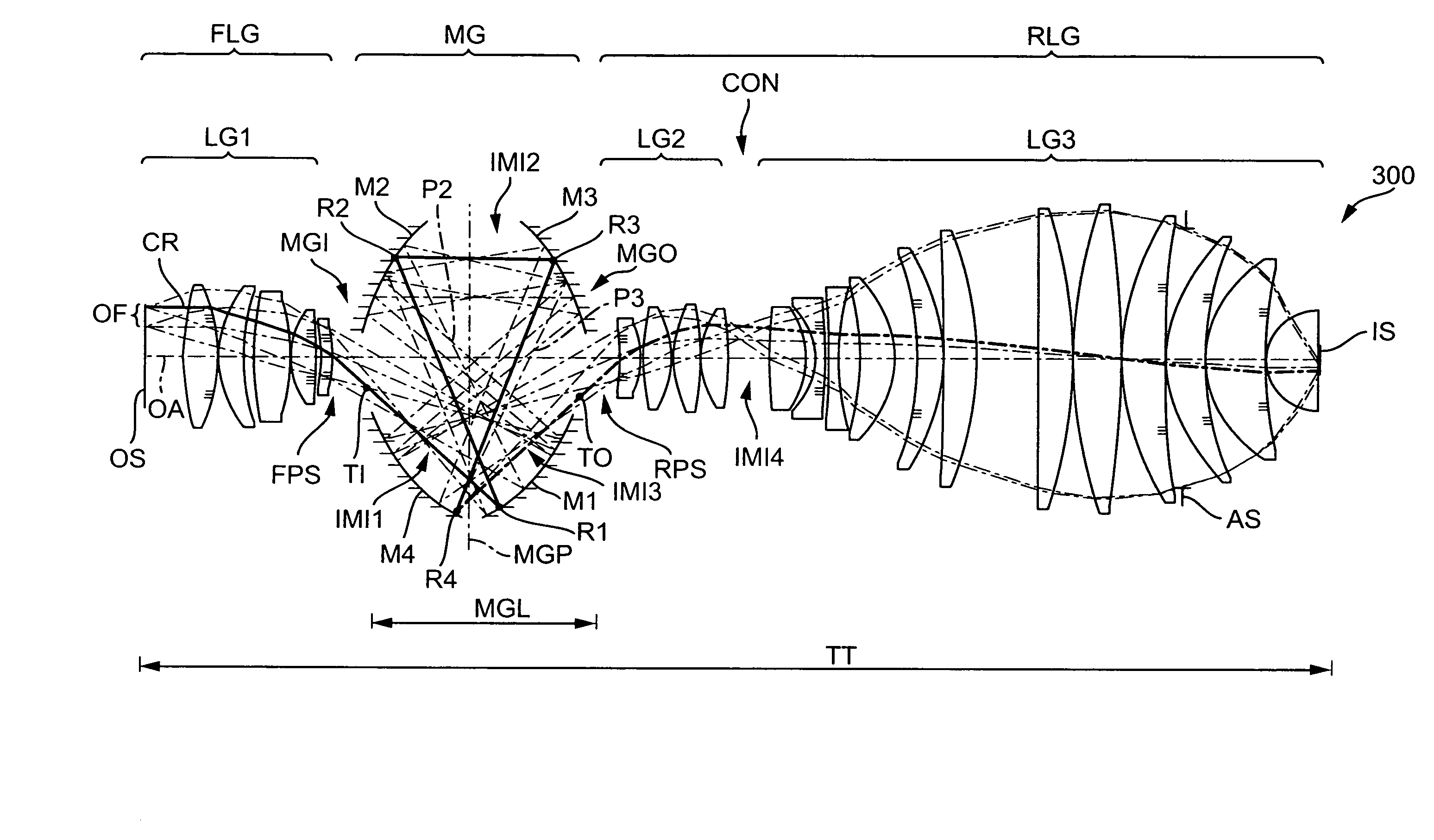
[0054] In the following description of preferred embodiments of the invention, the term “optical axis” shall refer to a straight line or sequence of straight-line segments passing through the centers of curvature of the optical elements. In the case of those examples presented here, the object is either a mask (reticle) bearing the pattern of an integrated circuit or some other pattern, for example, a grating pattern. In the examples presented here, the image of the object is projected onto a wafer serving as a substrate that is coated with a layer of photoresist, although other types of substrate, such as components of liquid-crystal displays or substrates for optical gratings, are also feasible.

[0055] Embodiments having a plurality of mirrors are described. Unless stated otherwise, the mirrors will be numbered according to the sequence in which the radiation is reflected on the mirrors. With other words, the numbering of the mirrors denotes the mirrors according to the position a...


PUM


Abstract

A catadioptric projection objective for imaging an off-axis effective object field arranged in an object surface of the projection objective onto an off-axis effective image field arranged in an image surface of the projection objective has: an optical axis; an effective object field situated entirely outside the optical axis and having a length A in a first direction and a width B in a second direction perpendicular to the first direction such that a circular area of minimum size enclosing the effective object field defines a radius REOF of the effective object field according to: REOF=(A / 2)2+(B / 2)2;and a circular design object field centered around the optical axis having a design object field radius RDOF, where the projection objective is essentially corrected with respect to image aberrations in zones having radial coordinates smaller than RDOF and wherein the projection objective is not fully corrected in zones having radial coordinates larger than RDOF. The conditions: RDOF=γ REOF and 1≦γ<1.4 are fulfilled. Very high image-side numerical apertures NA>1 are possible with a compact design. Arcuate effective object fields are preferably used.

Description

[0001] This application claims priority from U.S. provisional application 60 / 560,267 filed on Apr. 8, 2004. The complete disclosure of that provisional application is incorporated into this application by reference.BACKGROUND OF THE INVENTION [0002] 1. Field of the Invention [0003] The invention relates to a catadioptric projection objective for imaging an off-axis effective object field arranged in an object surface of the projection objective onto an off-axis effective image field arranged in an image surface of the projection objective. [0004] 2. Description of the Related Art [0005] Catadioptric projection objectives are, for example, employed in projection exposure systems, in particular wafer scanners or wafer steppers, used for fabricating semiconductor devices and other types of micro-devices and serve to project patterns on photomasks or reticles, hereinafter referred to generically as “masks” or “reticles,” onto an object having a photosensitive coating with ultrahigh reso...

Claims


Application Information

Patent Timeline
IPC IPC(8): G02B17/08G02B17/06G03F7/20
CPCG02B17/0812G02B17/0816G02B17/0844G02B17/0848G02B17/086G02B17/0892G03F7/70058G03F7/70275G03F7/70341G02B17/0804G02B17/0808G02B17/0836G03F7/70225G02B17/06G02B17/08
Inventor EPPLE, ALEXANDER
Owner CARL ZEISS SMT GMBH
Why Eureka
Try Eureka