Method for Applying Solder to Redistribution Lines

Inactive Publication Date: 2007-12-27
POLARIS INNOVATIONS
View PDF9 Cites 2 Cited by
  • Summary
  • Abstract
  • Description
  • Claims
  • Application Information

AI Technical Summary

Benefits of technology

[0009] As one advantageous feature, embodiments of the invention minimize the expenditure for producing a solder resist mask.

Problems solved by technology

A disadvantage of this method is that additional laborious process steps, such as coating, exposing, developing and curing, are required for the creation of the solder resist mask, with the effect of increasing production expenditure.

Method used


Image

  • Method for Applying Solder to Redistribution Lines
  • Method for Applying Solder to Redistribution Lines
  • Method for Applying Solder to Redistribution Lines

Examples


Embodiment Construction

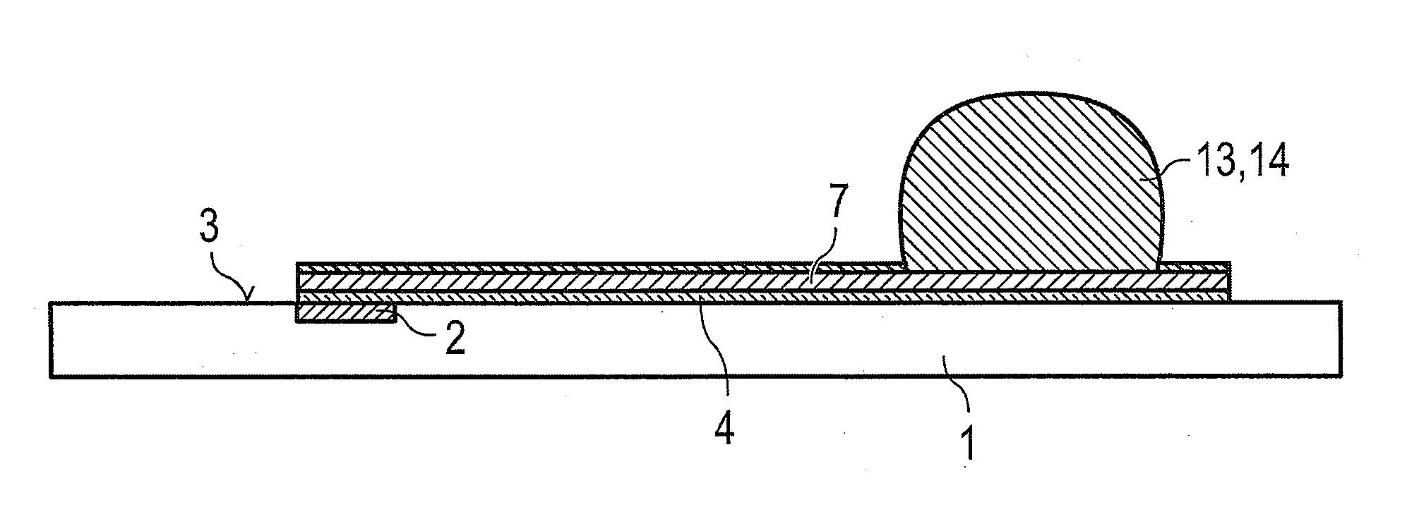
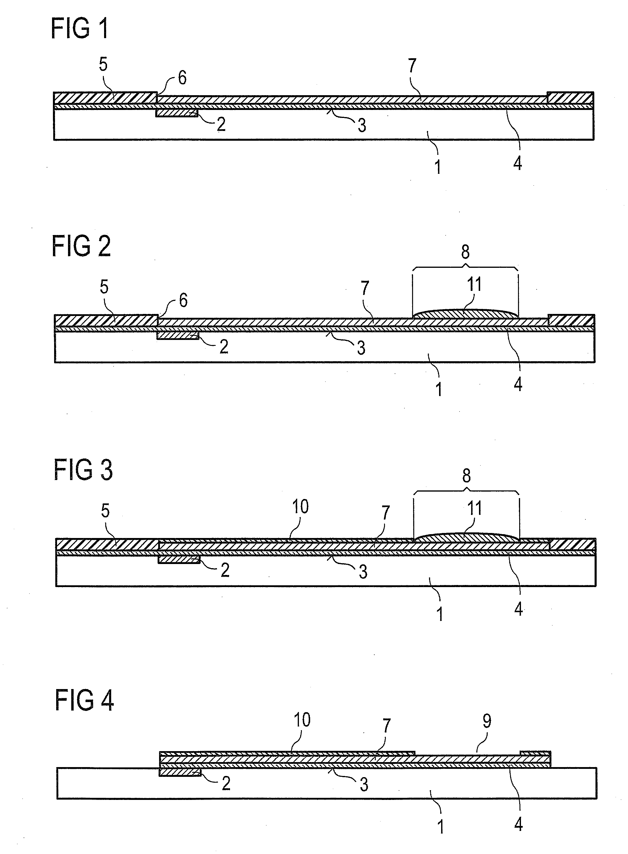
[0035] As represented in FIG. 1, contact points 2 are arranged on the semiconductor chip 1. The contact points 2 are connected in an electrically conducting manner to a circuit structure (not represented any more specifically) in the semiconductor chip 1. In order to connect these contact points 2 to corresponding contact points on a substrate that is not represented any more specifically, it is necessary to perform a redistribution. For this purpose, a seed layer 4 is deposited onto the surface 3 of the semiconductor chip 1. The seed layer 4 serves for the contacting of the entire surface 3 with respect to an electrical potential for the later electrolytic deposition of layers.

[0036] The upper side of the seed layer 4 is provided with a mask 5. The mask 5 is provided with mask openings 6. As represented in FIG. 1, a copper layer is deposited in the region of the mask opening 6 and forms a redistribution line 7 as a consequence of the structuring by way of the mask opening.

[0037] ...


PUM


Abstract

In a method of making an electronic component, an electrically conductive redistribution line is formed on a surface of a semiconductor chip. The redistribution line includes a solder pad. A covering material is formed over the solder pad and an uncovered portion of the redistribution line is passivated. The covering material prevents passivation of the solder pad. Solder is then formed over the solder pad such that the uncovered portion of the redistribution line has solder resist properties due to the passivating.

Description

[0001] This application claims priority to German Patent Application 10 2006 028 811.4, which was filed Jun. 21, 2006 and is incorporated herein by reference. TECHNICAL FIELD [0002] An embodiment of the invention relates to a method for applying solder to redistribution lines. BACKGROUND [0003] In the mounting of semiconductor chips, it is known to provide the surface of the semiconductor chips with solder, in order to mount the semiconductor chips on a substrate and connect them in an electrically conducting manner by means of this solder. [0004] An electrically conducting connection is produced between a contact point on the surface of the semiconductor chip and a corresponding contact point on the substrate. Since the contact points on the substrate are generally located at a different position than the contact points on the surface of the semiconductor chip, redistribution lines are provided between the contact points on the surface of the semiconductor chip and contact points o...

Claims


Application Information

Patent Timeline
IPC IPC(8): H01L21/44
CPCH01L24/11H01L2224/1147H01L2924/0001H01L2224/131H01L2924/014H01L2224/13099H01L2224/16H01L2924/01029H01L2924/01079H01L24/13H01L2924/01005H01L2924/01006H01L2924/01033H01L2224/05024H01L2224/05022H01L2224/05548H01L2224/05001H01L2224/05647H01L24/05H01L24/02H01L2224/023H01L2924/00014
Inventor TROVARELLI, OCTAVIOREISS, MARTINZIMMERMANN, BERND
Owner POLARIS INNOVATIONS
Why Eureka
Try Eureka