Small droplet sprayer
- Summary
- Abstract
- Description
- Claims
- Application Information
AI Technical Summary
Benefits of technology
Problems solved by technology
Method used
Image

Examples
example 1
Small Droplet Atomizer
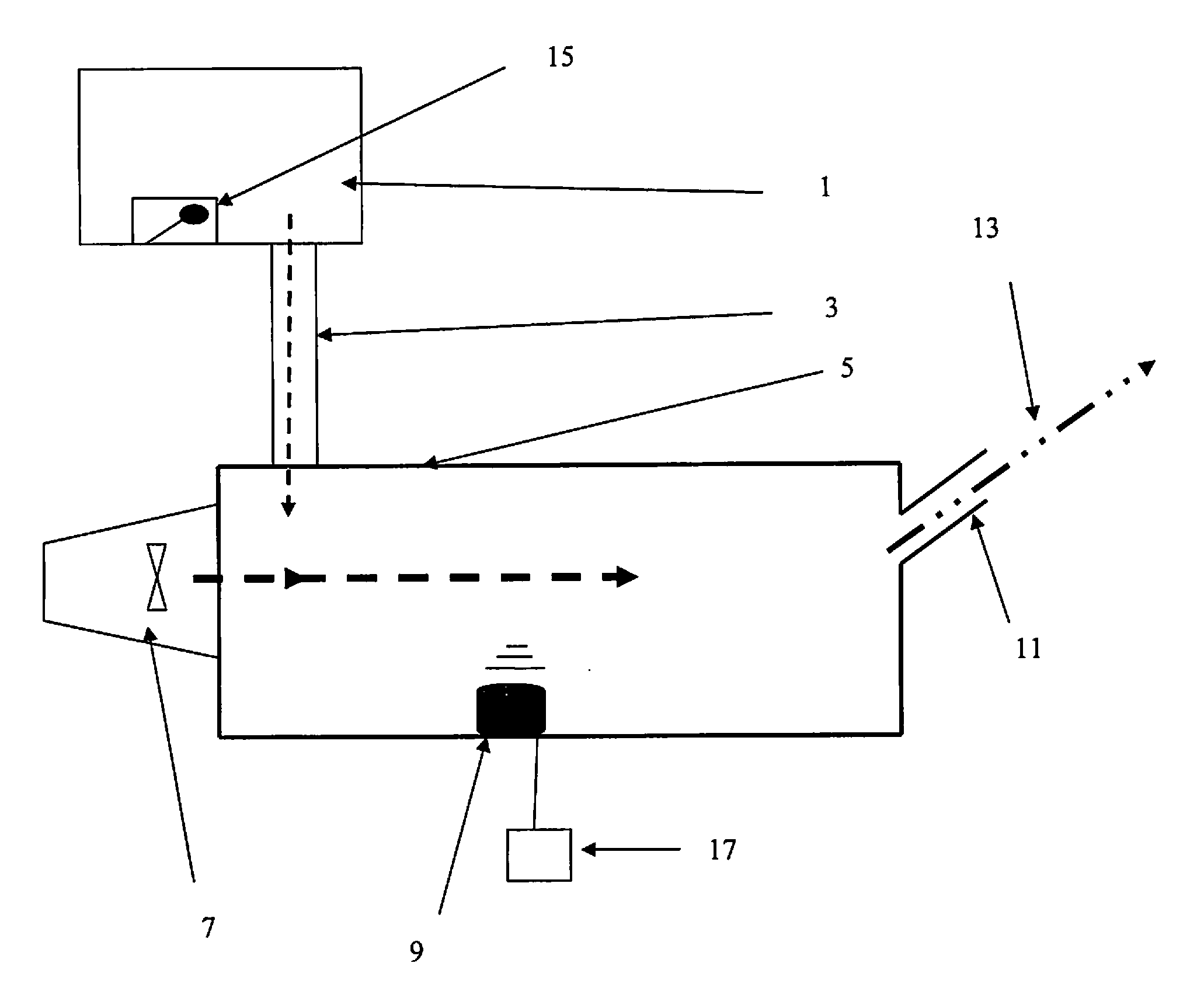
[0015]In a preferred embodiment, the inventive device is capable of producing and expelling droplet sizes of liquids, defined as 5 μm or smaller. The device comprises a reservoir (1), connected, via a connection tube (3) capable of permitting fluid to pass to a transducer drum (5). The transducer drum contains one or more transducers (9) that are electrically connected to a suitable power source (17). The power source (17) is capable of generating electrical oscillations in the ultrasonic frequency range. Ultrasonic frequency range is defined as a frequency of oscillation above 19 kHz.
[0016]As an example, in one embodiment, the ultrasonic frequency is approximately 0.8 MHz to approximately 1.7 MHz. Power switching with the power switching transistor can be arranged as Colpitts oscillator. In a preferred embodiment, the frequency is 1.65 MHz.
[0017]Any type of transducer can be utilized, including magnetostrictive or piezo-electric transducers. In a preferred emb...
example 2
Charged Droplet Atomizer
[0023]Flying insects generate an electrical charge as they move through the air. As such, negatively charged particles would be attracted to those regions of the flying insect that have imparted a positive charge.
[0024]Procedures and devices have been described capable of generation of charged droplets. In general, this is conducted by exposing of droplets to a suitable electrical field (Ahn, et al., Biomicrofluidics 3, 044102 (2009); Pilat and Lukas, Air and Waste Manage. Assoc. 54: 3-7 (2004)). Exposing fluids to an electric field is also utilized in electrostatic spray devices and methods (Stark, et al., U.S. Patent Application 2010 / 0155496 (Jun. 24, 2010)); Imai, et al., U.S. Patent Application 2012 / 0153055 (Jun. 21, 2012)).
[0025]In one embodiment of the current device, illustrated in FIG. 2, fluid from the reservoir (1) flows through the connection tube (3) and is discharged into the transducer drum (5). In the transducer drum (5), the fluid is subjected...
example 3
Method of Applying Insecticide by Electrostatic Droplets
[0028]In applying insecticide sprays to flying insects, current methods typically entail spraying in the vicinity of the insects and the insects encountering the spray by random collisions with the droplets. Furthermore, since insecticide droplets are typically relatively large, often over 50 μm in diameter, the droplets tend to settle relatively quickly. The rapid settling of insecticide necessitates application of large amounts of material at a height to enable adequate collisions of the insects with the insecticide droplets. The result is that significant amounts of insecticide, which is wasted and not actually encountered by the insect, in order to afford efficacy of the spraying with adequate coverage of area.
[0029]In one embodiment, small, 5 μm diameter droplets, or less, are created with the device described in Example 1. Application of insecticide is then applied to the desired area creating a slow settling fog, since t...
PUM
 Abstract
Description
Claims
Application Information
 - R&D
- Intellectual Property
- Life Sciences
- Materials
- Tech Scout
- Unparalleled Data Quality
- Higher Quality Content
- 60% Fewer Hallucinations
Browse by: Latest US Patents, China's latest patents, Technical Efficacy Thesaurus, Application Domain, Technology Topic, Popular Technical Reports.
© 2025 PatSnap. All rights reserved.Legal|Privacy policy|Modern Slavery Act Transparency Statement|Sitemap|About US| Contact US: help@patsnap.com