Wafer delivery device with door

A wafer and container technology, applied in the field of wafer carrying devices, can solve the problems that passive elastic pads are difficult to manufacture and use

Inactive Publication Date: 2004-01-21
ENTEGRIS INC
View PDF0 Cites 0 Cited by
  • Summary
  • Abstract
  • Description
  • Claims
  • Application Information

AI Technical Summary

Problems solved by technology

The large containers required to load large wafers make common passive resilient spacers difficult to manufacture and use

Method used


Image

  • Wafer delivery device with door
  • Wafer delivery device with door
  • Wafer delivery device with door

Examples


Embodiment Construction

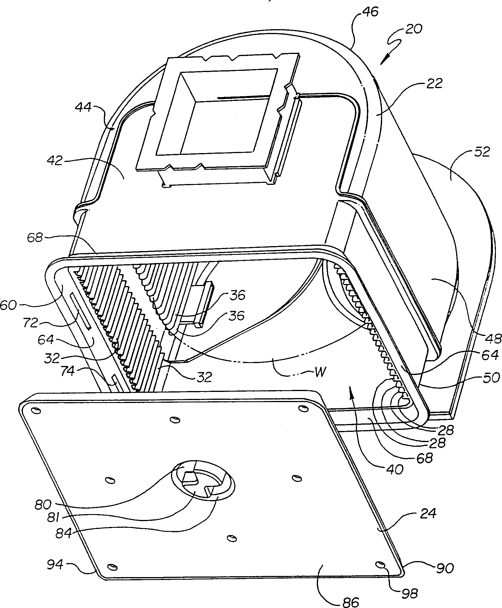
[0036] see figure 1 , the wafer container 20 generally includes a container portion 22 and a cooperating door 24 . The container portion has wafer recesses 28 for inserting and removing wafers W substantially in a horizontal plane. The recess is formed by the wafer guide 32 and the wafer support frame 36 . The container portion has an open front 40 , a closed upper part 42 , a closed left side 44 , a closed back 46 , a closed right side 48 and a closed bottom 50 . The shown container is located on a device interface 52 .

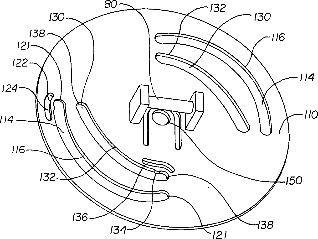
[0037] Door 24 is disposed within and attached to door mounting frame 60 . The door frame 60 has two pairs of opposing frame members, a pair of vertical members 64 and a pair of horizontal members 68 . The vertical frame member has a pair of slots or grooves 72, 74 for attaching and locking the door in the container portion 22. There is a rotatable member 80 in the central part of the door and a manual or automatic handle 81 in a recess 84 in the front ...


PUM


Abstract

A wafer container has an open front defined by a door frame and a door sized for the door frame. The door receiving frame has slots on opposite sides and the door utilizes latching portions that extend and retract from the edge portion of the door into and out of the slots for latching and unlatching the door on the door receiving frame. The door also has wafer engaging arms which extend inwardly toward the wafers to secure said wafers when the door is in place. The retractable latching portions and wafer retaining arms are linked to a rotatable cammed member in the interior of the door. The cammed member utilizes cammed surfaces configured to first latch the door and to then extend the wafer retaining arms.

Description

technical field [0001] The present invention relates to a wafer carrier. More particularly, it relates to a wafer container with a lid or door to enclose the wafer in the container. Background technique [0002] Various methods are used to enclose wafers in containers for storage and transport. Some containers use wafer vertical grooves and covers or covers made of resilient, flexible plastic. When the upper cover is used to connect the wafer, the passive spacers attached to the upper cover will be deflected. [0003] The semiconductor industry has grown to process large wafers greater than 300 mm in diameter, and carriers and shipping containers also tend to hold wafers horizontally. The large containers required for loading large wafers make conventional passive resilient spacers difficult to manufacture and use. [0004] The wafer container has an open front formed by a door frame and a door sized to fit the door frame. There are grooves on opposite sides of the door...

Claims


Application Information

Patent Timeline
Patent Type & Authority Patents(China)
IPC IPC(8): B65D51/26B65D6/40B65D85/86H01L21/673
CPCH01L21/67373H01L21/00H01L21/68
Inventor D·L·尼塞施
Owner ENTEGRIS INC
Why Eureka
Try Eureka