
Cellulose Acylate Film, Process for Producing Cellulose Acylate Film, Polarizing Plate and Liquid Crystal Display Device

a technology of cellulose acylate film and polarizing plate, which is applied in the direction of polarizing elements, lighting and heating apparatus, instruments, etc., can solve the problems of difficult compatibility between the display of retardation and the prevention of bleedout, and the uniformity of in-plane retardation

Active Publication Date: 2007-12-27
FUJIFILM CORP
View PDF4 Cites 18 Cited by
  • Summary
  • Abstract
  • Description
  • Claims
  • Application Information

AI Technical Summary

Benefits of technology

[0006] An object of the invention is to provide a cellulose acylate film free from the occurrence of facial failure such as bleed-out and having uniform and high retardation.
[0007] Another object of the invention is to provide a cellulose acylate film free from the occurrence of facial failure such as bleed out, having high retardation, and uniform in in-plane retardation.
[0008] A further object of the invention is to provide a liquid crystal display having high angle of visibility and high grade display in which a polarizing plate using the cellulose acylate film is used.
[0009] The present inventors have found that retardation can be greatly exhibited without causing facial failure such as bleed-out by the addition of a retardation raising agent having polarizability anisotropy and the distance between terminals of a molecule respectively in specific ranges to a cellulose acylate film in an amount of from 0.1 to 30 mass %. (In this specification, mass % and mass parts are equal to weight % and weight parts, respectively.) It has also been found that the degree of orientation of the retardation raising agent conspicuously increases, so that it becomes possible to greatly and uniformly exhibit retardation by stretching the cellulose acylate film containing the retardation raising agent on specific conditions. The present invention has been achieved on the basis of the knowledge.

Problems solved by technology

However, although a certain effect can be obtained with these methods, a great amount of additive must be used when further higher retardation is required, so that there arises a problem that the exhibition of retardation and the prevention of bleed-out are difficult to be compatible.
Further, there is another drawback that in-plane retardation becomes not uniform.

Method used


Image

  • Cellulose Acylate Film, Process for Producing Cellulose Acylate Film, Polarizing Plate and Liquid Crystal Display Device
  • Cellulose Acylate Film, Process for Producing Cellulose Acylate Film, Polarizing Plate and Liquid Crystal Display Device
  • Cellulose Acylate Film, Process for Producing Cellulose Acylate Film, Polarizing Plate and Liquid Crystal Display Device

Examples


synthesis example 1

Synthesis of Exemplified Compound (A-1)

[0397] A reaction vessel equipped with a stirrer, a material feeder, a reflux condenser and a thermometer having a capacity of 1,000 ml was charged with 40.1 g (189 mmol) of 2,4,5-trimethoxybenzoic acid, 16.75 g (90 mmol) of 4,4′-dihydroxy-biphenyl, 200 ml of toluene, and 2 ml of dimethylformamide, and the reaction mixture was heated at 70° C. After that, 23.6 g (198 mmol) of thionyl chloride was slowly dropwise added thereto, and the mixture was heated at 70° C. for 2.5 hours with stirring. Thereafter, the reaction solution was cooled to room temperature, and 300 ml of methanol was added. A crystal precipitated was recovered by filtration to thereby obtain 48.4 g (yield: 94%) of a compound of the object as a white crystal. Incidentally, the compound was identified by 1H-NMR (400 MHz).

[0398]1H-NMR (CDCl3): δ3.93 (s, 6H), 3.95 (s, 6H), 3.99 (s, 6H), 6.58 (s, 2H), 7.28 (d, 4H), 7.62 (m, 6H)

[0399] The resulting compound had a melting point of f...

synthesis example 2

Synthesis of Exemplified Compound (A-2)

[0400] The same reaction vessel as used in Synthesis Example 1 was charged with 34 g (160 mmol) of 2,4,5-trimethoxybenzoic acid, 15 g (73 mmol) of 4,4′-dihydroxy-3-fluorobiphenyl, 110 ml of toluene, and 1.6 ml of dimethylformamide, and the reaction mixture was heated at 70° C. After that, 20.9 g (176 mmol) of thionyl chloride was slowly dropwise added thereto, and the mixture was heated at 70° C. for 2.5 hours with stirring. Thereafter, the reaction solution was cooled to room temperature, and 300 ml of methanol was added. A crystal precipitated was recovered by filtration to thereby obtain 37 g (yield: 86%) of a compound of the object as a white crystal. Incidentally, the compound was identified by 1H-NMR (400 MHz).

[0401]1H-NMR (CDCl3): δ3.93 (s, 6H), 3.95 (s, 6H), 4.00 (s, 6H), 6.59 (s, 2H), 7.26-7.45 (m, 5H), 7.63 (m, 4H)

[0402] The resulting compound had a melting point of from 197 to 199° C.

synthesis example 3

Synthesis of Exemplified Compound (A-3)

[0403] The same reaction vessel as used in Synthesis Example 1 was charged with 23.3 g (110 mmol) of 2,4,5-trimethoxybenzoic acid, 15 g (50 mmol) of 4,4′-dihydroxy-3-chlorobiphenyl, 75 ml of toluene, and 1.1 ml of dimethylformamide, and the reaction mixture was heated at 70° C. After that, 14.4 g (121 mmol) of thionyl chloride was slowly dropwise added thereto, and the mixture was heated at 80° C. for 2.5 hours with stirring. Thereafter, the reaction solution was cooled to room temperature, and 250 ml of methanol was added. A crystal precipitated was recovered by filtration to thereby obtain 26 g (yield: 85%) of a compound of the object as a white crystal. Incidentally, the compound was identified by 1H-NMR (400 MHz).

[0404]1H-NMR (CDCl3): δ3.90-4.00 (m, 18H), 6.59 (s, 2H), 7.26-7.70 (m, 9H)

[0405] The resulting compound had a melting point of from 168 to 170° C.


PUM

PropertyMeasurementUnit
Fractionaaaaaaaaaa
Fractionaaaaaaaaaa
Fractionaaaaaaaaaa

Abstract

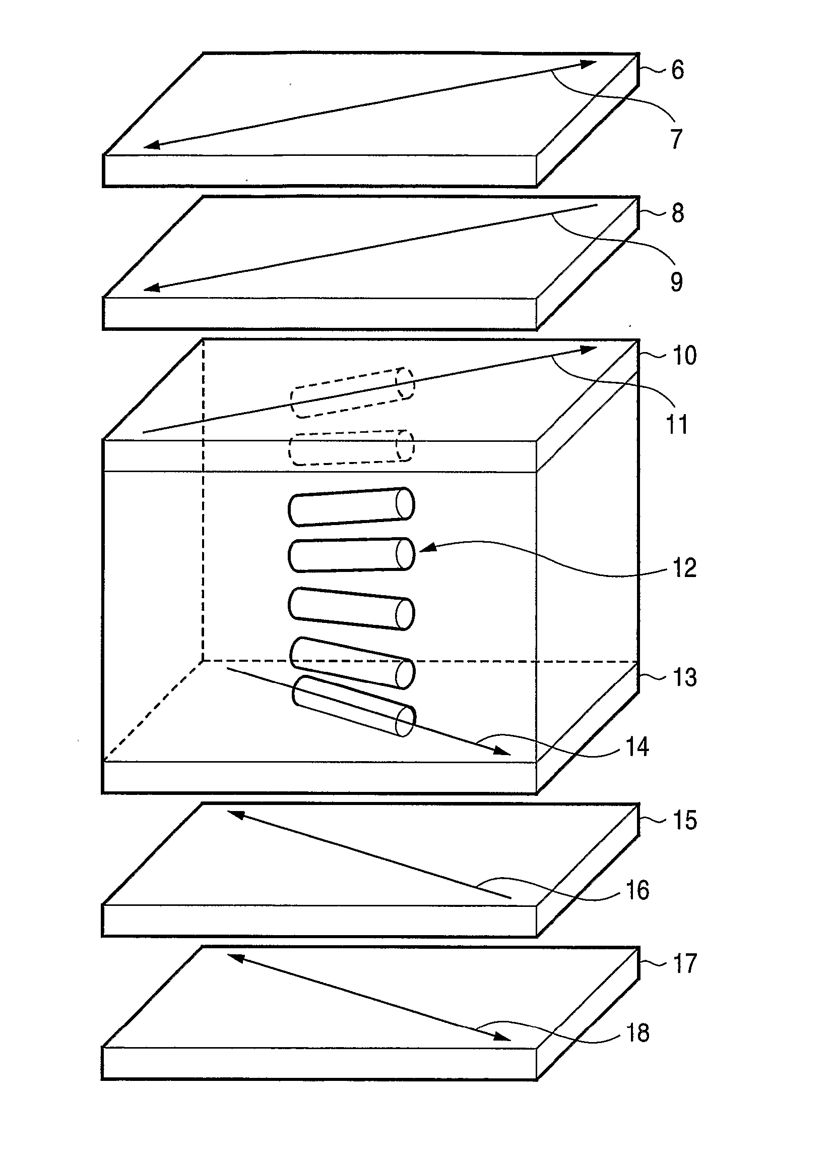
A cellulose acylate film comprising at least one retardation raising agent having specific rod-like polarizability anisotropy or specific plane polarizability anisotropy, and specific distance between terminals of a molecule in a specific amount; a process for producing the same; and a polarizing plate and liquid crystal display using the same.

Description

TECHNICAL FIELD [0001] The present invention relates to a cellulose acylate film, a process for producing a cellulose acylate film, and a polarizing plate and a display device using the same. BACKGROUND ART [0002] Liquid crystal displays are widening the usage year by year as image display apparatus requiring low consumption of electric power and a small space. Having large viewing angle dependency of images is a big defect of liquid crystal displays, however, liquid crystal modes such as VA mode and IPS mode having high angle of visibility have been put to practical use in recent years. As a result, the demand for liquid crystal displays is rapidly spreading also on the market requiring high angle of visibility such as televisions. [0003] With such a tendency, optical compensating films for use in liquid crystal displays are required to exhibit a broader range of retardation. A method of making a cellulose acylate film exhibit retardation to thereby impart the cellulose acylate fil...

Claims


Application Information

Patent Timeline
IPC IPC(8): C08L1/10B29C55/02C08J5/18G02B5/30G02F1/1335C08K5/04C08K5/16
CPCB29C55/04B29K2001/00B29K2001/12B29K2995/0034C08J5/18C08J2301/12Y10T428/105G02B5/305G02F1/133528G02F1/1395C08K5/04Y10T428/10C08L1/12C09K2323/00C09K2323/035C08K5/16C08L1/10G02F1/1335
Inventor FUKAGAWA, NOBUTAKAUCHIDA, OSAMUUEHIRA, SHIGEKIOGAWA, TOMOHIRO
Owner FUJIFILM CORP
Learn More