
Reactor tray vertical geometry with vitrified waste control

a vertical geometry and reactor tray technology, applied in nuclear reactors, nuclear elements, greenhouse gas reduction, etc., can solve the problems of a growing vehicle fleet, a growing industrial economy, and a loss of government support for alternative energy technologies such as solar, wind, and geothermal, and the u.s. appears to be heading toward another energy crisis

Inactive Publication Date: 2007-12-27
D B I CENTURY FUELS & AEROSPACE SERVICES
View PDF24 Cites 10 Cited by
  • Summary
  • Abstract
  • Description
  • Claims
  • Application Information

AI Technical Summary

Benefits of technology

[0011] DBI's report Thorium to Hydrogen (Library of Congress Control Number 2003097825) shows the limitations of current sources of energy, including fossil fuels, solar cells, ocean energy, hydroelectric dams, and wind turbines. Although nuclear energy has not been promoted as an alternative due to the human health and environmental safety risks associated with current reactor designs, the reactor of the present invention drastically reduces—if not eliminates—many of the dangers associated with conventional nuclear reactors.
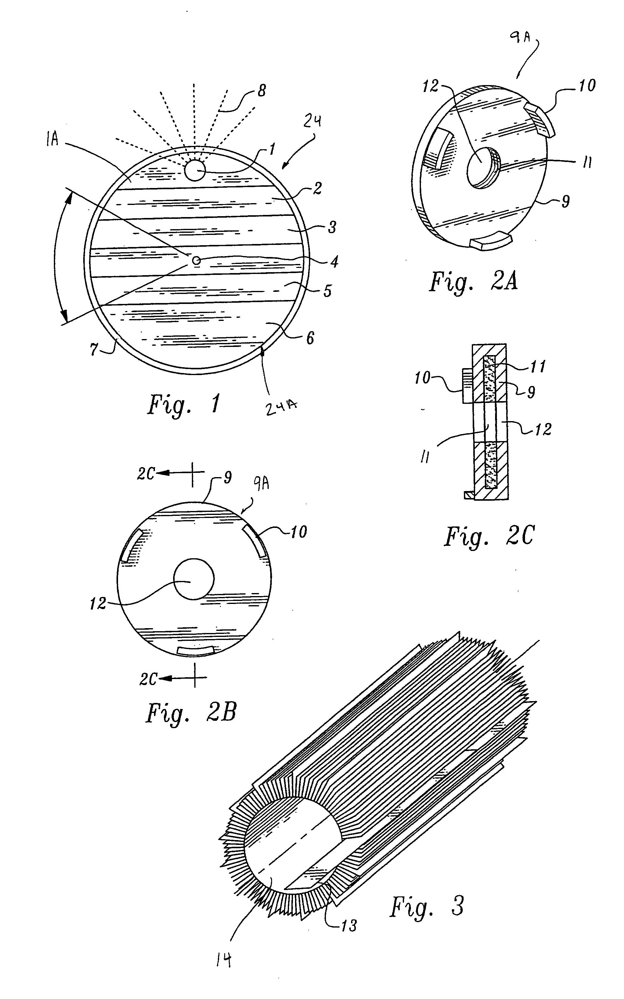
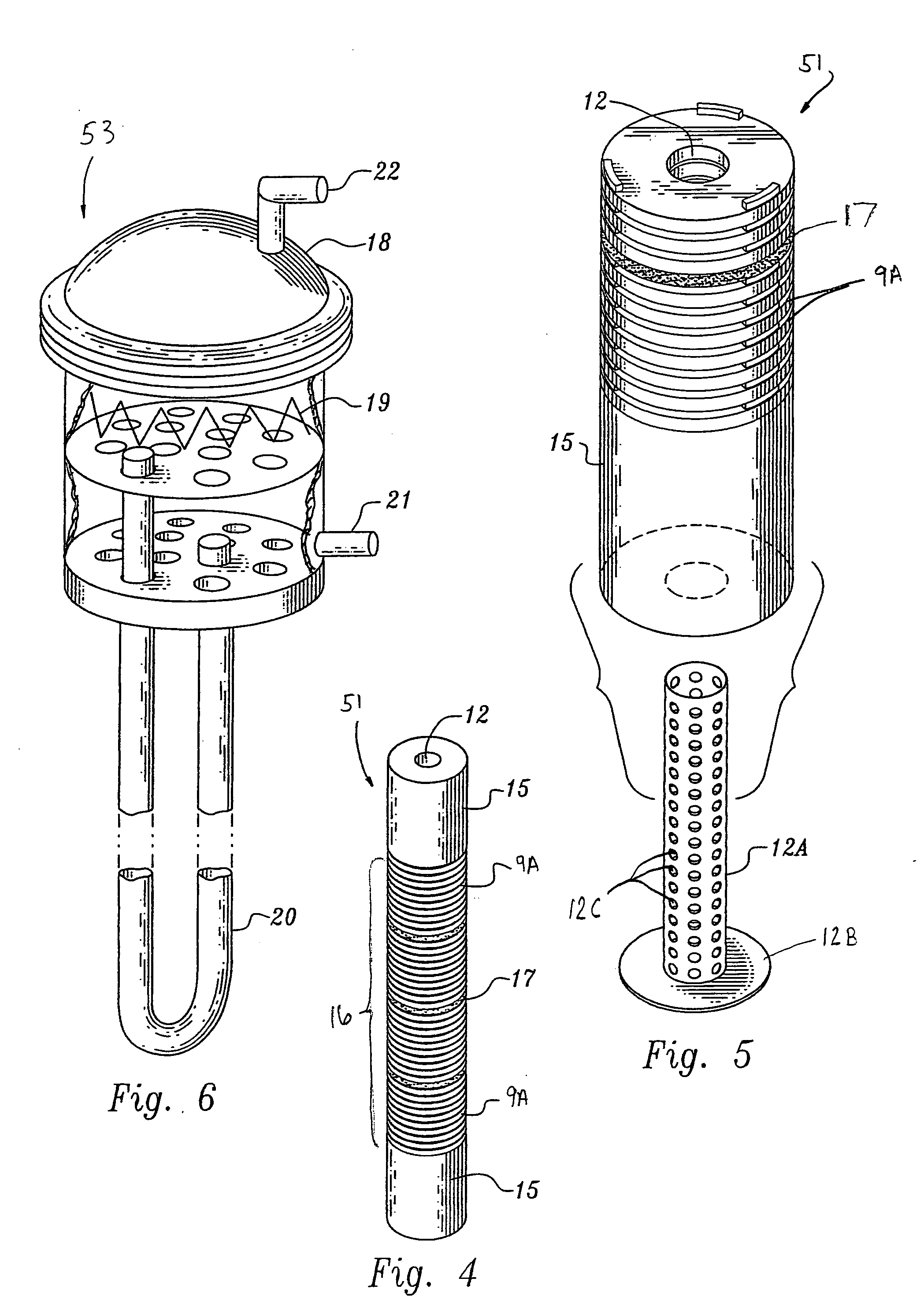
[0013] One of the most prominent aspects of the present invention is the fuel system. The unique design of the present invention allows for a fuel burn-up rate of about 90%, reduces the amount of waste by about 90% from current reactor designs, and produces no weapons grade material. When compared to conventional uranium-based nuclear reactors, the thorium design concept of the present invention eliminates the current problems of high waste production, negative environmental impact, proliferation of nuclear weapons material, reactor instability with possibility of meltdown, system complexity, and high operating costs. The present invention may be used in any application which uses a heat source to generate steam for a thermodynamic cycle (such as driving turbines) to generate electricity, pump water, or extract hydrogen.
[0014] With a single-phase helium coolant, a graphite moderator, and carbon reflectors, the present invention uses a multiple cavity fuel element, with fuel in the form of thorium oxide and glass in pre-baked tablets containing 50% SiO2, 47% 232ThO2, 3% 233UO2 in some configurations. A 90% burn rate is possible because the present invention allows the fuel to remain in the core until it is totally burned, something not possible in conventional reactors. In a shutdown mode, the fuel of the present invention is solid vitrified matter, providing an impervious, tamper-proof container for the spent fuel. This design is fundamentally different from conventional reactor core designs in multiple ways. The reactor of the present invention is subcritical, meaning it does not rely on a critical reaction to achieve the necessary neutrons. An external source of modulated neutrons makes possible the operation of the present subcritical reactor invention by an external neutron flux supply to bring the system up to a k=0.98 status in a safe and controllable manner. The neutron flux can be instantly stopped, controllably altered to new flux levels, or run at any neutron flux level needed, until the reactor of the present invention through fuel breeding develops its own ability to control power levels. The amount of breeding determines the neutron output flux level, and thereby the source can be slaved to the present invention's power level to maintain the exact power level desired, without fear of major core excursions.
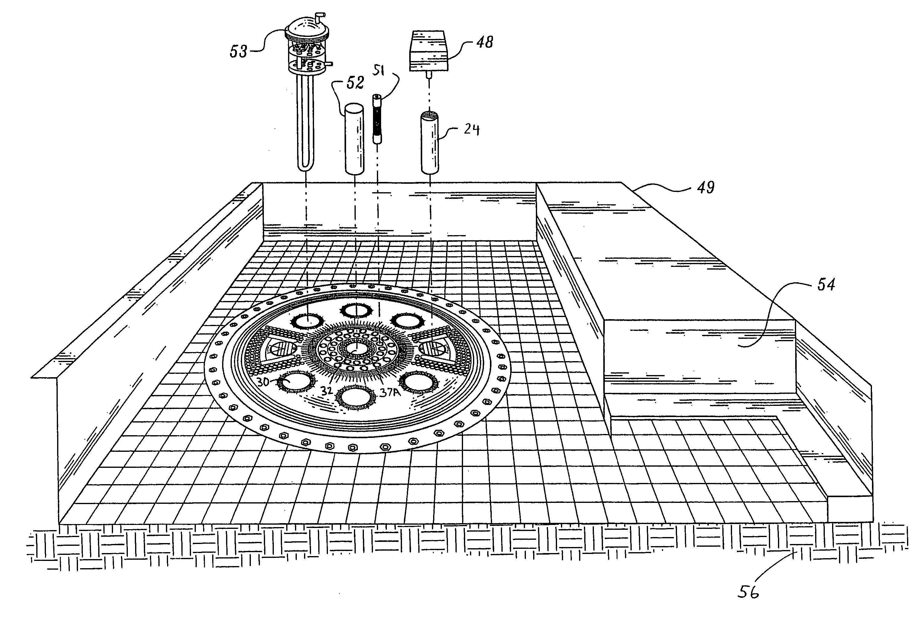
[0016] The present invention can be designed in a variety of sizes, ranging from as small as about 1 MW to more than about 100 MWs. This application contains one of multiple possible geometric designs in which the fuel can be switched from well to well. The attached figures represent a few specific embodiments for about a 100-MW plant. The power output, incidentally, will determine the physical size of the plant. The design allows it to be installed only about 18 feet below grade, thus eliminating the need to rely upon geological proof of deep ground stability.
[0017] The reactor of the present invention uses thorium as the energy source, which can then be used for the production of hydrogen—as a bridge from oil to fusion—while simultaneously reducing the volume of fuel loading and unburned fuel content using a new geometry for nuclear reactors. It can produce energy to extract hydrogen economically, with a significantly reduced amount of waste—all vitrified and containing only a minimal presence of useable 233U. The present invention provides maximum safety for startup, operation, and nuclear waste disposal. It is also innovative in its promotion of safety in connection with fueling startup, operation, shutdown, refining, and waste disposal. The configuration disclosed meets all the design performance requirements of simplicity, safety, reactor lifetime, reactor power output control, and economy of low investment and operational cost.

Problems solved by technology

Worldwide petroleum reserves needed to fuel power plants, a growing vehicle fleet, and an industrial economy are nearly depleted.
Additionally, alternative energy technologies—such as solar, wind, and geothermal—are losing governmental support.
Indeed, the U.S. appears to be heading toward another energy crisis due to governmental policies, public pressure, utility company shortsightedness, and corporate lack of incentives to either use alternative energy technologies or conserve energy.
In addition, the U.S. is confronted with environmental safety matters when using any sort of energy-generating method, whether a coal-fired plant or a solar plant.
An isolated and unsubstantiated laboratory experiment showed a slim possibility that fusion could be developed through relatively simple means at room temperature (Pons, B. Stanley, and Martin Fleishmann, University of Utah, 23 Mar. 23, 1989), but other experimental efforts to achieve such fusion have not been sustained.
However, many decades are still required to overcome the scientific and technological obstacles that prevent hot fusion from becoming a safe and affordable method of generating energy.
In the 1970s, dreams of energy surpluses based on nuclear power soon turned into energy shortages, followed in the 1980s by a glut that clouded the energy issue.
Over the years, the nuclear industry has attempted to push ahead with vast, costly projects that carry with them an array of human health and environmental safety risks.
These costs and risks have stunted the industry's growth: while world nuclear generating capacity grew by 140% in the 1980s, it expanded by less than 5% in the 1990s.
And proposed new construction will continue to result in the political opposition and public pressures that have blocked previous construction and stifled the industry's growth.
But, conventional nuclear power has serious drawbacks.
Specifically, production of a vast amount of extremely dangerous radioactive waste and lack of space for its disposal, potential for a meltdown that could release radioactivity, a byproduct that can be used for manufacturing nuclear weapons, and enormously high costs.
These drawbacks will continue to plague the industry, since conventional reactors will have produced enough waste within 10 years to completely fill the proposed waste storage site at Yucca Mountain, and require the use of uranium and the manufacture of weapons-grade plutonium.
These reactor plans, however, have been abandoned.
Thorium cannot be part of a conventional reactor without increasing the volume of waste disposal.
None of them have been carried forward, though, because the burnout rate of the thorium in conventional reactors is no different than that of plutonium, which calls for a large reprocessing plant.
Since current conventional energy-generating sources present grave hazards to public safety, health, and psychological well being, U.S. citizens are demanding a clean, safe, and domestically-produced energy source.
However, the most viable alternatives—hydrogen and electricity—are not energy sources but rather energy carriers that require a source of energy to start.

Method used


Image

  • Reactor tray vertical geometry with vitrified waste control
  • Reactor tray vertical geometry with vitrified waste control
  • Reactor tray vertical geometry with vitrified waste control

Examples


Embodiment Construction

[0102] While the present invention will be described with reference to a few specific embodiments, the description is illustrative of the invention and is not to be construed as limiting the invention. Various modifications to the present invention can be made to the preferred embodiments by those skilled in the art without departing from the true spirit and scope of the invention as defined by the appended claims. It will be noted here that for a better understanding, like components are designated by like reference numerals throughout the various figures.

[0103] In accordance with the present invention, some of the fundamental ideas of the reactor of the present invention are: (1) to drastically reduce the danger and the volume of nuclear waste; (2) to drastically reduce the size of the fuel charge in a reactor; (3) to eliminate weapons material in the waste stream; (4) to eliminate the need for reprocessing of nuclear fuel; and (5) to create a scenario where thorium will provide ...


PUM


Abstract

A nuclear-powered plant for systems of up to about 100 MWs with a confinement section where the reaction takes place in a core having a reactive thorium / uranium-233 composition, and where an external neutron source is used as a modulated neutron multiplier for the reactor core output. The core is housed in a containment structure that radiates thermal energy captured in a multiple-paths heat exchanger. The exchanger heat energy output is put to use in a conventional gas-to-water heat exchanger to produce commercial quality steam.

Description

RELATED APPLICATION DATA [0001] This is a Divisional Application of co-pending application Ser. No. 10 / 861,776 filed Jun. 3, 2004, which claims priority under 35 U.S.C. §119 to U.S. Provisional Application Ser. No. 60 / 476,144 naming Hector A. D'Auvergne as inventor, and filed Jun. 4, 2003, the entirety of which is incorporated herein by reference in its entirety for all purposes, and also claims priority under 35 U.S.C. §119 to U.S. Provisional Application Ser. No. 60 / 486,877 naming Hector A. D'Auvergne as inventor, and filed Jul. 10, 2003, the entirety of which is incorporated herein by reference in its entirety for all purposes.FIELD OF THE INVENTION [0002] The present invention relates to a nuclear reactor fueled by thorium-232 / uranium-233 (232Th / 233U) and driven by an exterior source of modulated neutrons. The criticality and power output of a graphite-reflected fuel cage and design concept is based on a subcritical assembly, where the thermal output is established on a per-unit...

Claims


Application Information

Patent Timeline
Patent Type & Authority Applications(United States)
IPC IPC(8): G21C7/00G21C1/00G21C1/30
CPCG21C1/00G21C1/30G21C3/62G21C7/34G21Y2002/304G21Y2002/50Y02E30/39G21Y2004/10G21Y2004/30G21Y2004/40Y02E30/37Y02E30/38G21Y2002/601Y02E30/30Y02E30/10
Inventor D'AUVERGNE, HECTOR A.
Owner D B I CENTURY FUELS & AEROSPACE SERVICES
Learn More