
Miniature acoustic transducer

a technology of acoustic transducer and a small body, applied in the field of miniature acoustic transducer, can solve the problems of insufficient effective deformation amount and design compliance, low resonant frequency response, and prone to fracture, and achieves low spring constant, high compliance and deformation amount, and increase diaphragm compliance

Active Publication Date: 2007-12-20
IND TECH RES INST
View PDF13 Cites 40 Cited by
  • Summary
  • Abstract
  • Description
  • Claims
  • Application Information

AI Technical Summary

Benefits of technology

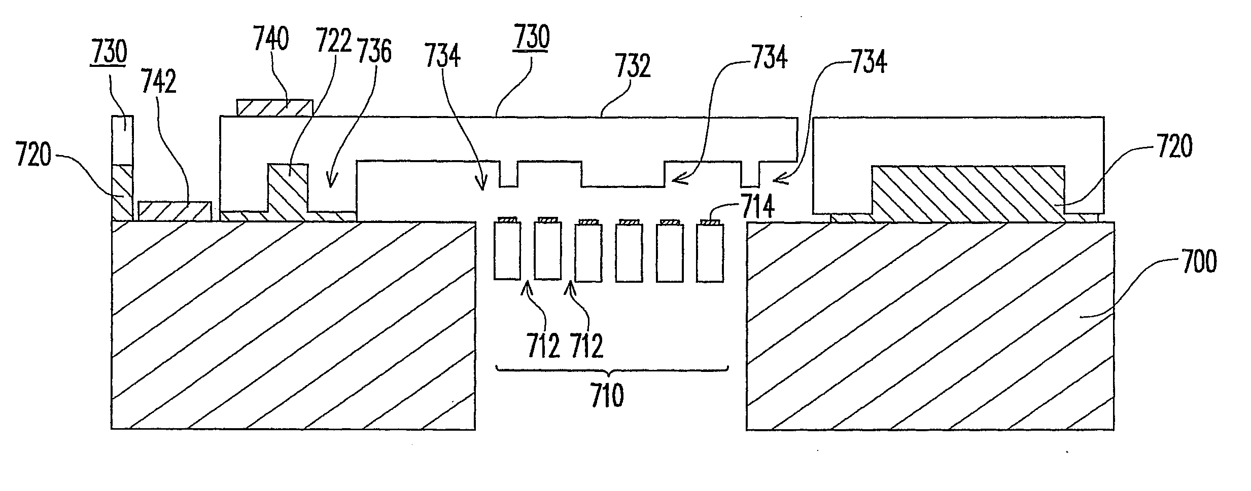
The present invention provides a new structure design for an acoustic transducer that increases diaphragm compliance and creates a low spring constant. This allows the transducer to have high compliance and deformation amount, resulting in improved performance. The invention includes a capacitive sound pressure sensing element with parallel plates and conductive material to constitute a capacitor, with acoustic holes formed on at least one of the parallel plates. The invention also includes a spring structure provided on at least one of the other parallel plates. The structural composition of the invention includes a substrate and a back plate with multiple acoustic holes, and a surface of the diaphragm with one or more indentations. The indentations contact the back plate to form a support structure, which increases the diaphragm deformation amount when a sound pressure is transmitted, resulting in increased sensing performance.

Problems solved by technology

Presently, the application of microphone element structures in mass production is limited to a few types of structures, because manufactories producing micro electro-mechanical systems (MEMS) microphones are currently only a few manufactories, such as Knowles Corp., Infineon Corp. or Sonion Corp., and most of the package processes on the market are still based on the designs developed by Knowles.
The diaphragm provides only a simple support, and although its structure can avoid the problem of residual stress and a high natural frequency response, the effective deformation amount and the compliance of its design are still inadequate.
Though the diaphragm of finger diaphragm design is soft and sensitive, it has a low resonant frequency response and is prone to fracture.
Though the diaphragm of corrugated diaphragm design can effectively reduce the influence of the residual stress to enable large diaphragm compliance, it has a complicated process and is difficult to be processed, and the increase in the compliance is limited.

Method used


Image

  • Miniature acoustic transducer
  • Miniature acoustic transducer
  • Miniature acoustic transducer

Examples


Embodiment Construction

[0025] The present invention provides an acoustic transducer, in which a bridge-like spring structure is constructed by fabricating a special structural pattern on a pressure sensing diaphragm in combination with indentations on the diaphragm as supports, utilizing the conception of a spring structure, so that the performance of the acoustic transducer is improved. The present acoustic transducer follows a principle that in order to effectively increase the compliance with a simple structure, the design pattern for the diaphragm may be changed and a structural effect similar to that of a spring may be produced via a support structure to increase the diaphragm compliance. The present invention provides a structure of a miniature acoustic transducer, which is useful in, for example, a miniature microphone element or any electronic device requiring sounds to be converted into signals, such as a handset or a miniature microphone, or any electronic device that detects variations in the a...


PUM


Abstract

A technique using a new diaphragm structure and support design is provided herein for microphones or structure designs for pressure sensing. The structure includes a set of capacitive structures. The capacitive structure has a combination of a diaphragm structure, a back plate structure and a surrounding micro-structure for fixing the diaphragm. After the diaphragm structure has deformed due to a pressure load, a gap between the back plate and the diaphragm is changed accordingly, and variation occurs in the capacitance value between the two parallel plates. By using the principle of the effect of capacitance value variation, the capacitive sensor causes the capacitance value to vary with the change in the sound, thus accomplishing the object of measuring.

Description

CROSS-REFERENCE TO RELATED APPLICATION [0001] The present invention claims the benefit of U.S. provisional patent application, Ser. No. 60 / 815,374, filed on Jun. 20, 2006. This application also claims the priority of Taiwan application serial no. 95149965, filed Dec. 29, 2006. All disclosure of the U.S. and Taiwan application is incorporated herein by reference.BACKGROUND OF THE INVENTION [0002] 1. Field of the Invention [0003] The present invention relates to a miniature acoustic transducer. More particularly, the present invention relates to a miniature acoustic transducer having a structure with a low spring constant. [0004] 2. Description of Related Art [0005] The acoustic transducer, produced by a capacitive microphone chip integrated through silicon micro-manufacturing technique and integrated circuit (IC) processing technique, has the advantages of a light mass, a small volume and a good signal quality etc. In applications of national home appliances products, as the demand f...

Claims


Application Information

Patent Timeline
Patent Type & Authority Applications(United States)
IPC IPC(8): H04R25/00
CPCH04R19/04
Inventor CHIEN, HSIN-TANGCHANG, PETERKUO, NAI-HAO
Owner IND TECH RES INST
Learn More