
Printing apparatus and printing method

a printing apparatus and printing head technology, applied in the direction of printing, other printing apparatus, etc., can solve the problems of reducing the life of normal print elements, reducing the durability of print heads, and reducing the lifetime of normal print elements. , the effect of minimizing the loss of durability of the print head

Inactive Publication Date: 2007-12-13
CANON KK
View PDF10 Cites 4 Cited by
  • Summary
  • Abstract
  • Description
  • Claims
  • Application Information

AI Technical Summary

Benefits of technology

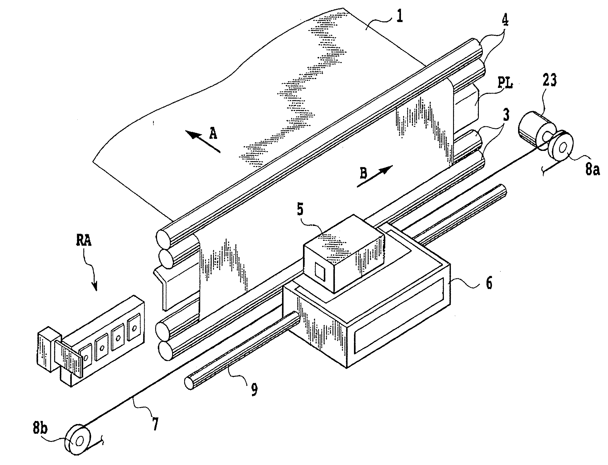
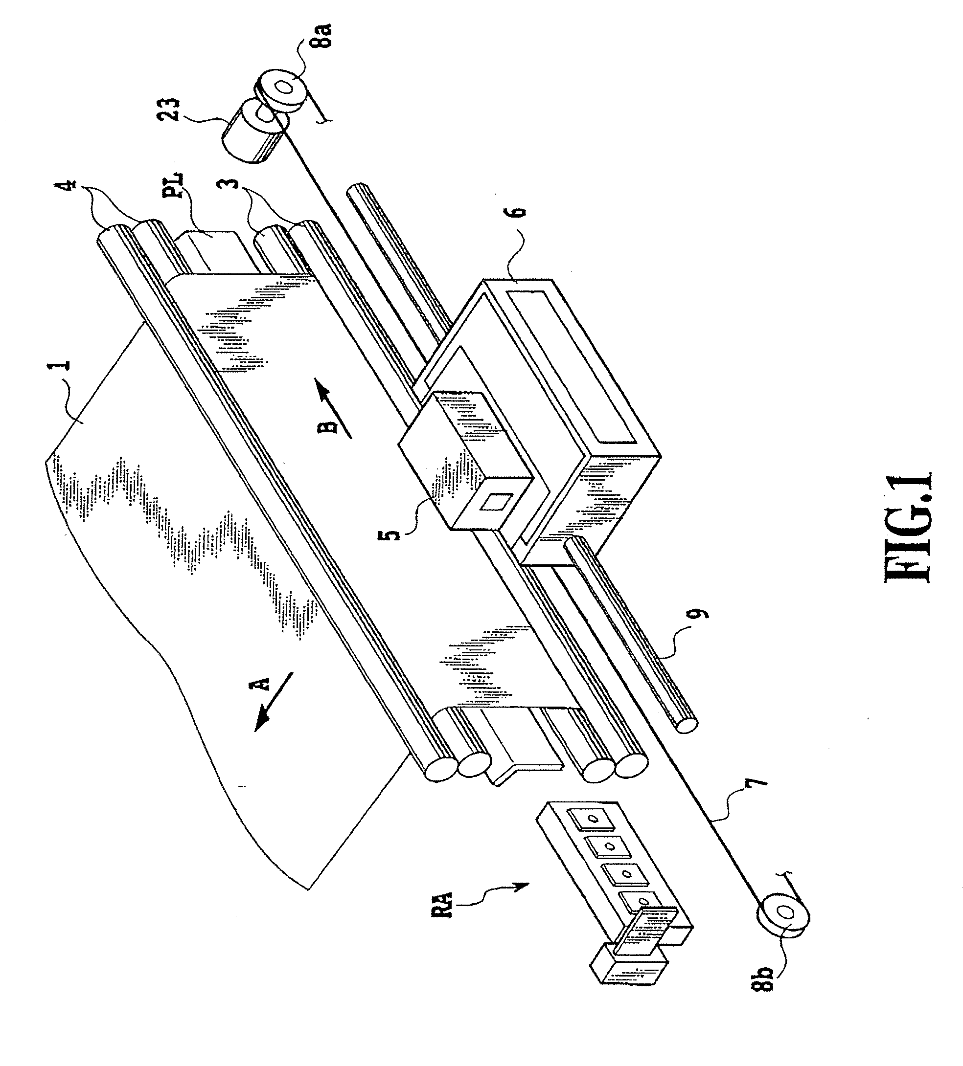
[0028] With the above configuration, when there are a plurality of defective print elements, not all the pixels otherwise printed by the plurality of defective print elements are to be corrected. However, defective print elements to be corrected are selected on the basis of the positional relationship among the defective print elements in a print head as well as various conditions for print media and ink. Then, other normal print elements are used to print only the pixels otherwise printed by the defective print elements selected. This makes it possible to achieve high-quality printing without wastefully reducing the lifetimes of normal print elements or minimizing the loss of durability of the print head.

Problems solved by technology

On the other hand, fine nozzles having a relatively small ejection opening diameter tend to provide ejection failure easily as compared with conventional nozzles having a large ejection opening diameter.
Further, in a bubble jet (trade mark) type in which electrothermal converters (heaters) are used to generate bubbles in ink to eject the ink from fine nozzles densely arranged, there is a possibility that any of the heaters are disconnected to preclude the ejection of the ink or ink droplets adhere to an ejection opening surface to cover the ejection openings, resulting in precluding the ejection of the ink.
Therefore, printing unstable that come from the ejection failure of the nozzles may be provided, resulting in degrading print images.
The presence of a nozzle from which ink cannot be ejected may result in forming lines which are not printed along a scan direction in print images.
Accordingly, it is difficult to obtain defect-free images
Consequently, the nozzles frequently used for the correction may early cause ejection mis-alignment in which an impacting position prematurely deviates from the regular one, irregular ejection in which an amount of ejection varies, or non-ejection.
However, in view of the lifetimes of normal nozzles used for the correction, every effort should be made to avoid the corrective printing.
However, since these image missing parts have been uniformly corrected in the past, even parts that are otherwise unperceived as the degradation of image even without corrections are corrected.
Consequently, there is a possibility that the lifetimes of normal nozzles wastefully shrink.
This problem also applies not only to ink jet printing apparatuses but also to other printing apparatuses that carry out printing using a plurality of print elements.
On the other hand, in the area intensively having a plurality of missing parts, these missing parts of printing are noticeable, thus missing parts of printing significantly affect the quality of the entire image.

Method used


Image

  • Printing apparatus and printing method
  • Printing apparatus and printing method
  • Printing apparatus and printing method

Examples


first embodiment

[0138] In the present embodiment, description will be given of a method for selecting non-ejection nozzles to be corrected, on the basis of the positional relationship among non-ejection nozzles in the print head 5.

[0139] First, description will be given of anon-ejection nozzle in the print head and how a white line appears.

[0140]FIG. 12 is a schematic diagram showing a white line appearing as a result of a failure to eject ink.

[0141] If there is any non-ejection nozzle in the print head 5, the raster to be printed by the non-ejection nozzle is not printed. Consequently, a white line appears in the image in the main scanning direction as shown in FIG. 12.

[0142]FIG. 12 shows 1-pass printing involving only one non-ejection nozzle. If there are a plurality of non-ejection nozzles, the appearance of white lines in the image varies depending on the positional relationship among the non-ejection nozzles in the print head 5.

[0143] Description will be given, by way of example, of a pri...

second embodiment

[0177] In the present embodiment, description will be given of the order in which if there are a plurality of combinations of non-ejection nozzles with a nozzle spacing of no more than a set value, nozzles to be corrected are selected from the non-ejection nozzles.

[0178] Description will be given of an example in which 1-pass printing and a nozzle spacing set value of 30 nozzles are used and in which the ink cannot be ejected from the nozzles having the nozzle numbers N100, N120, N200, N500, N510, N700, and N1100.

[0179] The nozzle spacing between non-ejection nozzles can be calculated on the basis of nozzle numbers. As shown in FIG. 20A, on the basis of the nozzle spacings calculated, combinations of non-ejection nozzles with a nozzle spacing set value of no more than 30 are a set of nozzles having the nozzle numbers N100 and N120 and a set of nozzles having the nozzle numbers N500 and N510. If there are a plurality of combinations with a nozzle spacing of no more than the set val...

third embodiment

[0187] The nozzle spacing set value need not be fixed. The corrective printing can be more effectively carried out by allowing the nozzle spacing set value to be varied depending on the types of print media or inks. In the present embodiment, description will be given of a method for varying the nozzle spacing set value depending on the types of print media.

[0188] The appearance of white lines caused by non-ejection nozzles depend heavily on the types of print media. For example, on print media on which impacting ink droplets are likely to spread, that is, to bleed, ink impacting pixels surrounding a dot missing pixel bleeds and spreads to the dot missing pixel. As a result, the area of the missing part is reduced to make the white line visually unnoticeable. On the other hand, on print medium on which ink droplets are unlikely to bleed, the impacting ink droplets do not widely spread, thus making clear the stripe part, from which dots are missing. Further, the appearance of white ...


PUM


Abstract

The present invention provides a printing method comprising a selecting method of selecting defective print elements to be corrected on the basis of, for example, the positional relationship among the defective print elements in a print head so that if there are a plurality of defective print elements such as non-ejection nozzles, not all pixels otherwise printed by the defective print elements are to be corrected but efficient corrections can be achieved on the basis of correlations with the lifetimes of other normal print elements, as well as a correcting method of making up for print data corresponding to the defective print elements selected, and a printing apparatus using the printing method.

Description

BACKGROUND OF THE INVENTION [0001] 1. Field of the Invention [0002] The present invention relates to a printing apparatus and a printing method which performs printing images on print media by using a print head composed of a plurality of print elements, and more specifically, to a printing method for printing so as to complement printing of a printing area to be otherwise printed by the defective print element by using another normal print element, if any of a plurality of print elements becomes defective, as well as a printing apparatus using the printing method. [0003] 2. Description of the Related Art [0004] Proposed printing apparatuses that print images on a printing medium such as a sheet of paper or OHP sheets are provided with print heads based on various printing method. The printing method of the print head includes a wire-dot type, a thermal type, a heat transfer type, or an ink-jet type. In particular, the ink jet type receives attention. This is because this method eje...

Claims


Application Information

Patent Timeline
Patent Type & Authority Applications(United States)
IPC IPC(8): B41J29/393
CPCB41J29/393
Inventor NAGAMURA, MITSUTOSHIKANEMATSU, DAIGOROTAKEKOSHI, RIEBABA, NAOKO
Owner CANON KK
Learn More