Side Illumination Lens and Luminescent Device Using the Same
a technology of luminescent devices and side illumination, which is applied in the direction of luminescent screens, discharge tubes, instruments, etc., can solve the problems of difficult application of the luminescent device to the backlight, complicated process of fabricating the lens, and limited use of conventional light emitting diodes. , to achieve the effect of reducing defective rate and fabrication costs of the lens, high output of light, and superior heat dissipation
- Summary
- Abstract
- Description
- Claims
- Application Information
AI Technical Summary
Benefits of technology
Problems solved by technology
Method used
Image
Examples
embodiment 1
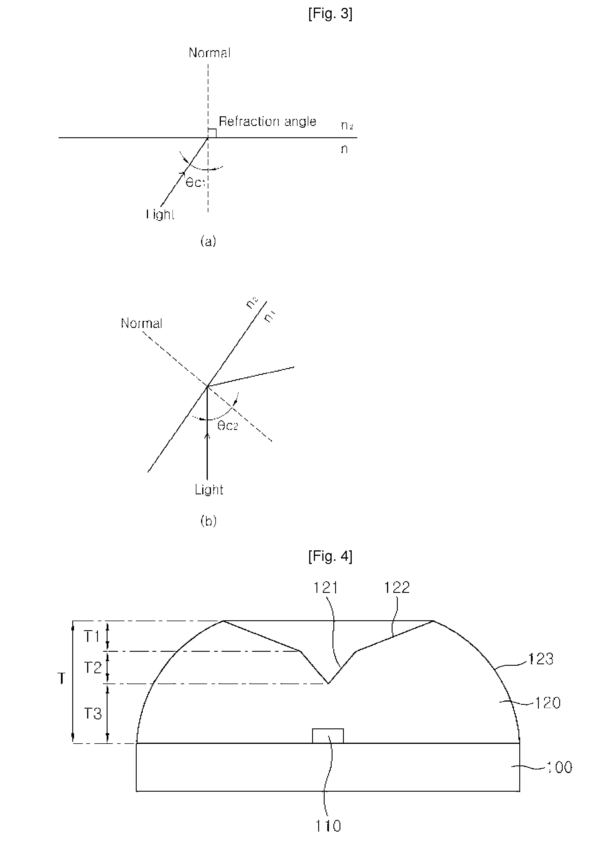
[0060]FIG. 4 is a sectional conceptual view of a luminescent device with a lens according to a first embodiment of the present invention, FIG. 5 is a plan view of the lens according to the first embodiment, FIG. 6 is a conceptual view illustrating the operation of the total internal reflection lens according to the first embodiment, FIG. 7 is a graph showing simulation results of the luminescent device with the lens according to the first embodiment, and FIGS. 8 and 9 are graphs showing experimental measurement results.
[0061] Referring to FIGS. 4, 5 and 6, the luminescent device with the lens according to this embodiment comprises a substrate 100; a luminescent chip 110 mounted on the substrate 100; and a lens that encapsulates the luminescent chip 110 and has a V-shaped first total reflection surface 121 with a predetermined slope with respect to a central axis, a second total reflection surface 122 extending outward therefrom with a slope smaller than that of the first total refl...
embodiment 2
[0161]FIG. 29 is a conceptual sectional view of a luminescent device with a lens according to a second embodiment of the present invention, FIG. 30 is a perspective of the lens according to the second embodiment, FIG. 31 is a conceptual view illustrating the operation of the total internal reflection lens according to the second embodiment, and FIG. 32 is a graph showing simulation results of the luminescent device according to the second embodiment.
[0162] Referring to FIGS. 29, 30 and 31, the lens of this embodiment comprises a first total reflection surface 1121 with a V-shaped section and a certain slope with respect to a central axis x; a second total reflection surface 1122 with a slope smaller than that of the first total reflection surface 1121; a linear first refractive surface 1123a extending from a periphery of the second total reflection surface 1122 in a direction perpendicular to the central axis x; and a curved second refractive surface 1123b extending downward from a...
embodiment 3
[0177]FIG. 33 is a conceptual sectional view of a luminescent device with a lens according to a third embodiment of the present invention, FIG. 34 is a perspective view of the lens according to the third embodiment, FIG. 35 is a conceptual view illustrating the operation of the total internal reflection lens according to the third embodiment, and FIG. 36 is a graph showing simulation results of the luminescent device according to the third embodiment.
[0178] Referring to FIGS. 33, 34 and 35, the lens of this embodiment comprises a first total reflection surface 2121 with a V-shaped section and a certain slope with respect to a central axis x; a second total reflection surface 2122 with a slope smaller than that of the first total reflection surface 2121; a curved first refractive surface 2123a extending downward from a periphery of the second total reflection surface 2122; a linear second refractive surface 2123b extending from a periphery of the first refractive surface 2123a in a ...
PUM
 Abstract
Description
Claims
Application Information
 - R&D
- Intellectual Property
- Life Sciences
- Materials
- Tech Scout
- Unparalleled Data Quality
- Higher Quality Content
- 60% Fewer Hallucinations
Browse by: Latest US Patents, China's latest patents, Technical Efficacy Thesaurus, Application Domain, Technology Topic, Popular Technical Reports.
© 2025 PatSnap. All rights reserved.Legal|Privacy policy|Modern Slavery Act Transparency Statement|Sitemap|About US| Contact US: help@patsnap.com


