
EUV-lithography apparatus having a chamber for cleaning an optical element

a technology of euv lithography and optical elements, which is applied in the field of projection exposure systems, can solve the problems of contamination and/or disruption of the optical surface of the components, the introduction of contaminants into the optical system, and the first and last optical surfaces, etc., to achieve the effect of cleaning the contaminated optical elements regularly and increasing the use tim

Inactive Publication Date: 2007-12-13
CARL ZEISS SMT GMBH
View PDF15 Cites 13 Cited by
  • Summary
  • Abstract
  • Description
  • Claims
  • Application Information

AI Technical Summary

Benefits of technology

[0015] The object of the invention is thus to offer an optical subsystem of a projection exposure system that is characterized in that the use times are increased in comparison to the devices known from the prior art. According to the invention, this is achieved by the fact that at least one optical element of the optical subsystem has a surface which is at least twice as large as the dimensions of the first used area on this optical element. By this measure, it can be achieved that an optical area on the mirror or a transmissive optical element can be regularly removed from the beam path in the optical subsystem and is cleaned, while a cleaned used area remains in the beam path. In this manner, it is possible to clean the contaminated optical elements regularly without interrupting the operating time of the machine.
[0016] It is particularly advantageous if the first used area and the used area(s) of the optical element have an identical optical effect. This is achieved in that the optical element is symmetric to a point of rotation, symmetric to an axis of rotation, or has several used areas with an identical optical effect, which are disposed along a translation axis, which is also denoted a displacement axis.
[0024] In EUV lithographic systems, in addition to the formation of a separate vacuum chamber for cleaning purposes, it may also be provided that the optical element to be cleaned, in particular the optical mirror to be cleaned, is itself separated relative to the vacuum chamber of the rest of the system. An arrangement of the optical element to be cleaned in a separate vacuum chamber has the advantage that the mirror can be continually cleaned during operation by mixing in a specific oxygen concentration, and a full cleaning will be necessary only after longer operating times. Due to the arrangement in a separate vacuum chamber, the remainder of the system is protected, for example, from possible harmful effects of the cleaning. The optical subsystem is preferably an illumination system of a projection exposure system, but it can also be the projection objective itself, in which one or more optical elements according to the invention are formed, so that they allow a simple cleaning without interrupting operation.

Problems solved by technology

In projection exposure systems, which operate at wavelengths of ≦193 nm, in particular, in the range of ≦157 nm, particularly in the EUV range with wavelengths of <30 nm, the problem arises that radiation in the EUV- or VUV and DUV range, respectively, lead to a contamination and / or disruption of the optical surface of the components, which are also denoted optical elements.
The first and last optical surfaces, for example, of refractive systems are particularly at risk of contamination, since these are found in the direct vicinity, e.g., of a source, of a mask, or of a wafer to be exposed.
Contaminants are introduced into the optical system by these surfaces.
Such foils, however, lead to absorption and, in addition, introduce aberrations into the optical system.
The high-energy radiation of the light sources of ≦193 nm leads to the fact that, for example, the residual oxygen components are converted into ozone by the radiation, which in turn attacks and can disrupt the surfaces of the optical elements and their coatings.
In addition, contaminations can be formed on the optical surface due to concentrations of residual gas, such as hydrocarbons from the atmosphere surrounding the optical surface, e.g., due to crystal formation or layers, e.g, of carbon or carbon compounds.
The useful operating time of the machine is thus very sharply reduced in this way.

Method used


Image

  • EUV-lithography apparatus having a chamber for cleaning an optical element
  • EUV-lithography apparatus having a chamber for cleaning an optical element
  • EUV-lithography apparatus having a chamber for cleaning an optical element

Examples


Embodiment Construction

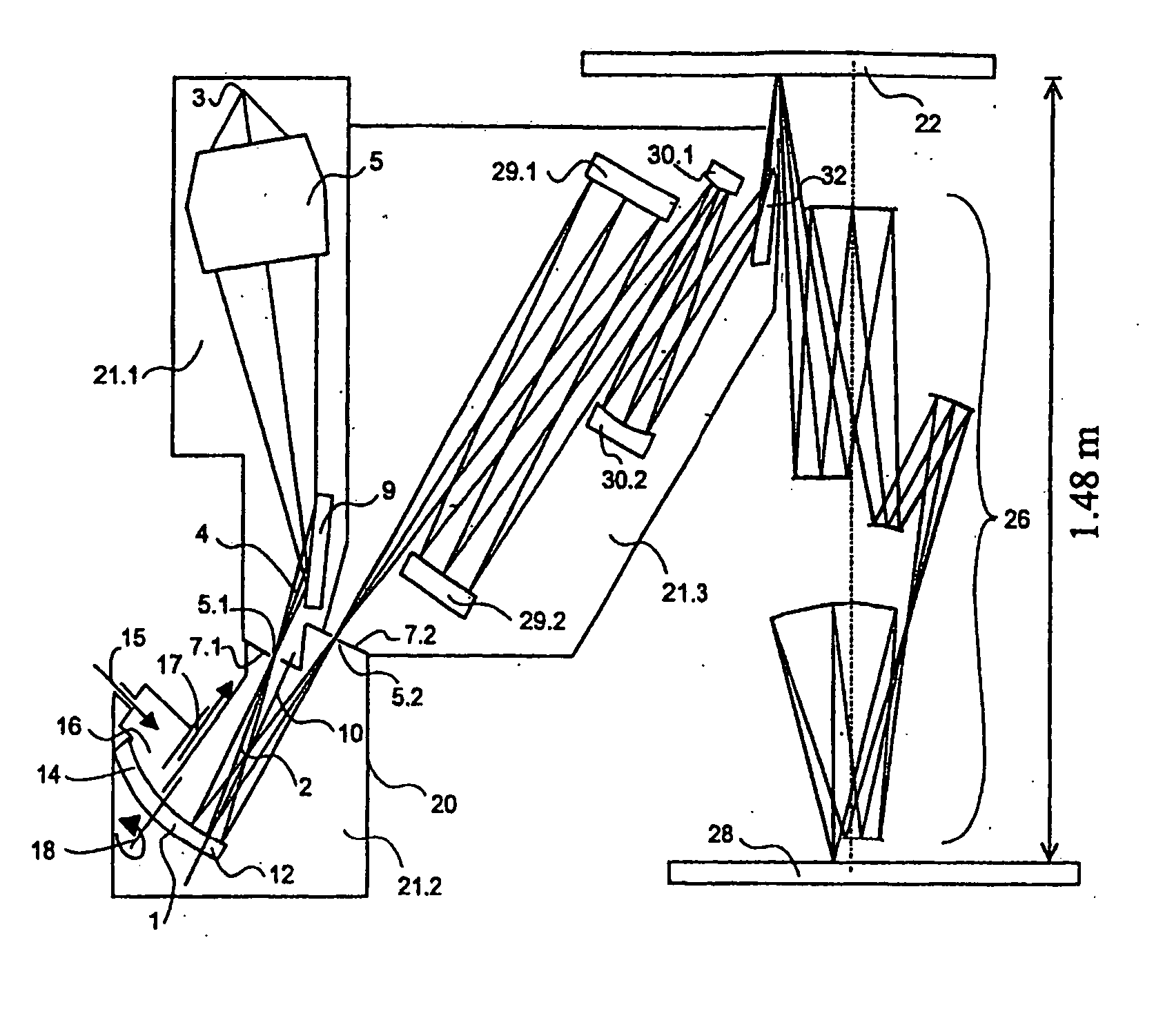
[0031]FIG. 1 shows an EUV projection exposure system with an optical element 1 according to the invention. The optical element 1 is a normal-incidence mirror, onto which rays 2 of a light bundle 4 from light source 3 to field plane 22 impinge at angles α12.

[0032] The dimensions of the optical element 1, here the normal incidence mirror, as can be seen from FIG. 1, are essentially larger than the first used area 12 of the mirror. The second used area 14 of the mirror is transported into a cleaning chamber 16 and is cleaned presently and not used.

[0033] Transport into the cleaning chamber 16 is conducted in the present case by turning around the axis of rotation 18. Other possibilities are also conceivable for transport into the cleaning chamber without departing from the basic concept of the invention. Such possibilities include the lateral transport of planar optical elements or the rolling, e.g., of spherical mirrors or concentric menisci.

[0034] As is clearly seen in FIG. 1, the...


PUM

PropertyMeasurementUnit
wavelengthaaaaaaaaaa
wavelengthsaaaaaaaaaa
widthaaaaaaaaaa

Abstract

There is provided, a system that includes (a) a source of light having a wavelength of less than or equal to about 193 nm, (b) an optical element having a region for directing the light, (c) an arrangement for cleaning the region, and (d) a chamber to accommodate the region during the cleaning.

Description

BACKGROUND OF THE INVENTION [0001] 1. Field of the Invention [0002] The invention relates to an optical subsystem, in particular for a projection exposure system, wherein a light bundle passes through the subsystem and the optical subsystem has at least one optical element, on which the rays of the light bundle impinge on a first used area. Projection exposure systems for microlithography, in particular for wavelengths of ≦193 nm have become known from a plurality of applications. Relative to catadioptric systems, reference is made to DE-A-100 20 592; relative to refractive systems, reference is made to DE 198 55 157 and DE-A-199 05 203, the disclosure content of which is incorporated in its entirety in the present application. The field of the invention includes the field of projection exposure systems, in particular, those that operate with EUV radiation. [0003] 2. Description of the Related Art [0004] At the present time, wavelengths in the range of 11-14 nm, in particular 13.5 n...

Claims


Application Information

Patent Timeline
Patent Type & Authority Applications(United States)
IPC IPC(8): F26B3/34G21K1/06G02B7/00G02B17/06G02B27/00G03F7/20H01L21/027
CPCG02B17/0657G02B27/0006G03F7/702G03F7/70975G03F7/70825G03F7/70925G03F7/70233
Inventor SINGER, WOLFGANGHAINZ, JOACHIMWIETZORREK, JOACHIMWEISS, MARKUS
Owner CARL ZEISS SMT GMBH
Learn More