
Method for manufacturing electroluminescent material

a technology of electroluminescent materials and manufacturing methods, which is applied in the manufacture of electrode systems, light compositions, electric discharge tubes/lamps, etc., can solve the problems of difficult to obtain characteristics, difficult to apply to medium or small displays, and high power consumption of inorganic el elements, so as to improve emission efficiency and life time, reduce the number of steps for operation, and ensure safety

Inactive Publication Date: 2007-12-06
SEMICON ENERGY LAB CO LTD
View PDF17 Cites 2 Cited by
  • Summary
  • Abstract
  • Description
  • Claims
  • Application Information

AI Technical Summary

Benefits of technology

[0012]In the view of the above problem, it is an object of the present invention to provide a manufacturing method of an electroluminescent material of which emission luminance, emission efficiency, and life time are improved as compared with a conventional material. In addition, it is an object of the present invention to provide a manufacturing method of an electroluminescent material with high safety, in which the number of manufacturing steps is reduced. Further, it is an object to provide a manufacturing method of an electroluminescent material utilizing a material including an element that is necessary for synthesis of the electroluminescent material but is to be an impurity to a light-emission mechanism. Furthermore, it is also an object to provide a light-emitting device and an electronic device utilizing an electroluminescent material synthesized in such a manner.
[0016]According to the present invention, an impurity giving adverse effect to light-emitting characteristics of an electroluminescent material can be reduced as much as possible, whereby emission luminance, emission efficiency, and life time can be improved as compared with a conventional material. In addition, when an electroluminescent material is manufactured by the present invention, the number of steps for operation can be reduced and the safety can be ensured.

Problems solved by technology

This characteristic is difficult to be obtained by a point light source typified by an incandescent lamp or an LED (Light Emitting Diode), or a line light source typified by a fluorescent lamp.
Therefore, the inorganic EL element has high power consumption and has been difficult to be applied to a medium or small-sized display, for example, a display of a mobile phone or the like.
However, in such a case, the base material itself is decomposed when baking at a high temperature is conducted, and a material having a defect may be manufactured after the baking.
There is a problem in that such a defect may give adverse effect to characteristics such as emission luminance of an inorganic EL element.
Accordingly, work and handling of the material becomes increasingly dangerous.

Method used


Image

  • Method for manufacturing electroluminescent material
  • Method for manufacturing electroluminescent material
  • Method for manufacturing electroluminescent material

Examples


embodiment mode 1

[0050]In this embodiment mode, a manufacturing method of an inorganic EL material according to the present invention will be explained with reference to FIGS. 1A to 1D.

[0051]A manufacturing method of an inorganic EL material shown in this embodiment mode is a baking method using a sealed tube. As shown in FIG. 1A, in a sealed tube 2100 made of quartz or the like, which is sealed in a certain atmosphere, a crucible 2101 of alumina or the like and a crucible 2102 are separately disposed. The crucible 2101 contains a base material 2103, and the crucible 2102 contains an atmosphere material 2104 used for making an atmosphere in baking. It is to be noted that the above-described materials may be used for the base material 2103 and the atmosphere material 2104, and an impurity element that is to be a luminescent center may be added to the base material as an activator. Each material of the crucible 2101 and the crucible 2102 may be changed depending on a material to be contained. Here, in...

embodiment mode 2

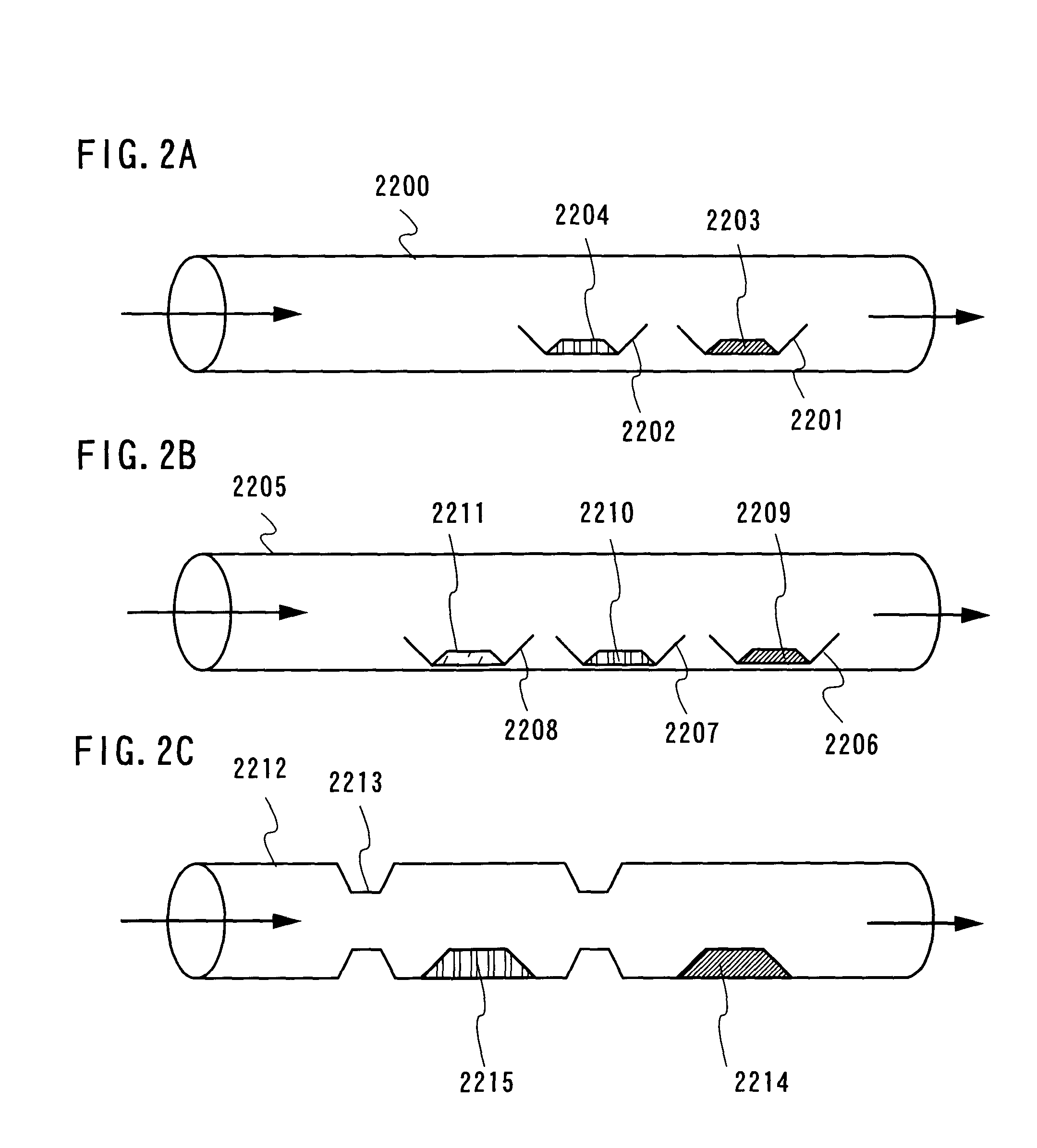
[0058]In this embodiment mode, a manufacturing method of an inorganic EL material according to the present invention will be explained with reference to FIGS. 2A to 2C.

[0059]A manufacturing method of an inorganic EL material shown in this embodiment mode is a baking method using an open tube. In a case where baking is performed in a horizontal tubular furnace as shown in FIG. 2A, a quartz tube is used as a core tube 2200, and a base material 2203 contained in a crucible 2201 and an atmosphere material 2204 contained in a crucible 2202 are provided in the core tube. At this point in time, the flow is produced in the open tube using an inert gas that is to be a carrier gas. Here, the atmosphere material 2204 is disposed in the upstream of flow of the carrier gas, whereby the base material 2203 can be exposed to an atmosphere of the atmosphere material 2204 in the core tube 2200 that is the open tube. As the base material and the atmosphere material, the above materials may be used, an...

embodiment mode 3

[0065]In this embodiment mode, a manufacturing method of an inorganic EL material according to the present invention will be explained with reference to FIGS. 3A and 3B.

[0066]A manufacturing method of an inorganic EL material shown in this embodiment mode is a baking method in a case of disposing samples vertically in an electric furnace. As shown in FIG. 3A, in a case of two materials, a sealed tube 2300 is provided with an orifice 2301, and a base material 2305 and an atmosphere material 2304 are provided therein. In the case of a vertical tubular furnace, a container such as a crucible cannot be fixed without a portion to be hung such as an orifice. First, a crucible 2302 is disposed at a bottom of a quartz tube one side of which is sealed, and an atmosphere material 2304 is contained. Next, the orifice 2301 is processed at a position separated from the crucible 2302. In the process, heating is performed with a burner or the like to make a hanging portion where a crucible 2303 ca...


PUM


Abstract

The present invention provides a manufacturing method of an inorganic EL material with high safety, in which the number of steps is reduced, in order to improve emission luminance, efficiency, or life time as compared with a conventional material. The present invention provides a manufacturing method of an inorganic EL material, in a case where a material is used, which is a necessary element or compound for synthesis of the inorganic EL material but includes an element to be unnecessary for the light-emission mechanism. Further, it is an object to provide a light-emitting device and an electronic device using the thusly synthesized inorganic material. In the present invention, a plurality of materials each of which vapor pressure is different are separately disposed in a sealed-tube container, and baking by heating are performed so that at least one of the materials is evaporated, whereby an electroluminescent material is manufactured by baking.

Description

BACKGROUND OF THE INVENTION[0001]1. Field of the Invention[0002]The present invention relates to a material for forming a light-emitting element, and particularly relates to a method for making an inorganic electroluminescent material.[0003]2. Description of the Related Art[0004]In recent years, a display device in a television set, a mobile phone, a digital camera, or the like has been required to be flat and thin, and a display device utilizing a self-luminous light-emitting element has attracted attention as a display device for meeting this requirement. A light-emitting element utilizing electroluminescence (hereinafter, also described as EL) is given as one of the self-luminous light-emitting elements. In this light-emitting element, a light-emitting material is interposed between a pair of electrodes and light emission from the light-emitting material can be obtained by applying a voltage.[0005]Such a self-luminous light-emitting element has advantages that visibility of a pix...

Claims


Application Information

Patent Timeline
IPC IPC(8): H01J9/00
CPCC09K11/623C09K11/612
Inventor OHARA, HIROKIHIRAKATA, YOSHIHARU
Owner SEMICON ENERGY LAB CO LTD
Learn More