Optical disc, information recording method, information reproducing method, and disc drive

Inactive Publication Date: 2007-12-06
KK TOSHIBA
View PDF19 Cites 24 Cited by
  • Summary
  • Abstract
  • Description
  • Claims
  • Application Information

AI Technical Summary

Benefits of technology

[0095] (9) A write-once, multi-layer (dual-layer) optical disc which performs recording and reproducing upon irradiation of a laser beam having a wavelength of 600 nm or less, comprises one or more molded substrates each having a groove formed in a concentric shape or spiral shape (and pits having information) used as a guide for reading out information, one of the one or more molded substrates has a burst cutting area on which specific information (BCA record, etc. in FIG. 2A) unique to the disc is recorded at a specific wavelength (one wavelength falling within the range from 600 nm to 800 nm: for example, 650 nm), and recording and reproducing of information are allowed by forming recording layers of an organic dye on the one or more molded substrates, wherein a groove (104) is formed on the burst cutting area to store the organic dye material, thereby increasing a sensitivity of this organic dye material to the specific wavelength (e.g., 650 nm).

Problems solved by technology

However, when high-frequency components of the response characteristics are emphasized, since noise components are emphasized at the same time, errors due to such noise components also increase.
Therefore, it is difficult for the conventional signal processing method to dramatically increase the recording density.
Since the reproduction waveform causes a distortion by the waveform interference from neighboring bits, data cannot be determined by only 1 bit unlike in the conventional method.
In this way, when the waveform slice method is used as the signal detection method, signal deterioration components increase even when the density increases by any method, and data can no longer be correctly decoded.
However, it is demanded for optical disc drives, players, and recorders to have reproduction (playback) compatibility of various types of discs, and disc discrimination becomes harder to attain.
Upon making an attempt to form a BCA by mastering BCA, since the dye fills in a BCA pattern on the molded substrate, a BCA signal with a high CN is hard to obtain.
However, it is difficult for both mastering BCA and post-cut BCA to “form a BCA on the L1 layer”, and a BCA is formed on the L0 layer in the specification.

Method used


Image

  • Optical disc, information recording method, information reproducing method, and disc drive
  • Optical disc, information recording method, information reproducing method, and disc drive
  • Optical disc, information recording method, information reproducing method, and disc drive

Examples


example 2

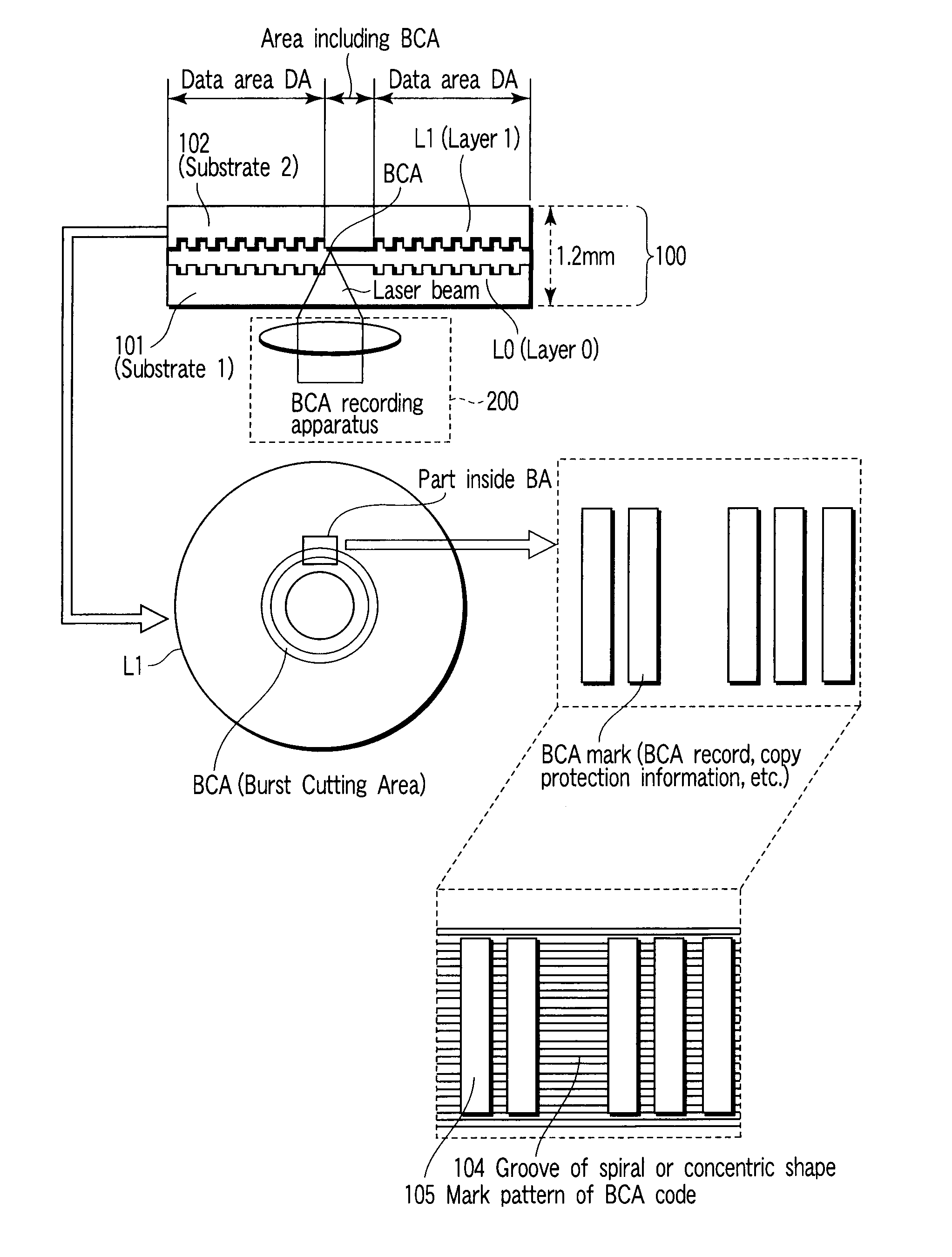
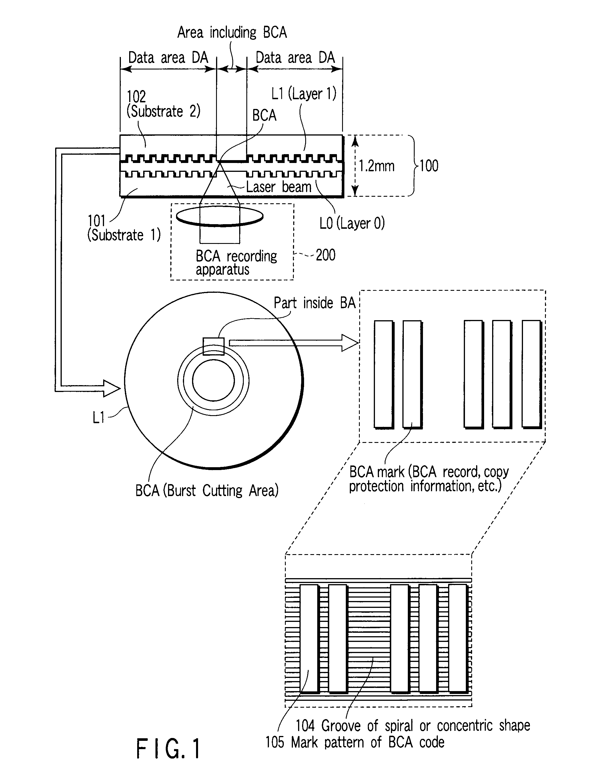
[0079] In the disc of Example 1 described with reference to FIG. 1 and the like, the dye thickness is earned by the effect of groove 104 which is formed in advance (in other words, the volume of the dye which absorbs the energy of a laser in unit time increases), thus increasing the recording sensitivity upon BCA formation. However, in addition, adjusting an organic dye component used in the layer on which the BCA is to be formed is also an effective method in terms of improvement of the recording sensitivity upon BCA formation. That is, for example, in a dual-layer HD_DVD-R disc, since the BCA is formed only on the L1 layer, the organic dye of the L1 layer is adjusted.

[0080] A pre-production disc of Example 2 is prepared under the following conditions. After an L0 layer using a recordable organic dye which had an absorption near 405 nm is formed, an L1 substrate pattern is transcribed or transferred on the L0 layer using a photopolymer, and an L1 organic dye is further applied by ...

example 3

[0082] The write-once, dual-layer discs pre-produced by the methods of Examples 1 and 2 underwent BCA part signal evaluation. An evaluation apparatus is an optical disc evaluator having an optical head which has laser wavelength λ: 405 nm and numerical aperture NA: 0.65 of an objective lens of an optical pickup. The arrangement of the evaluation apparatus will be described below.

[0083]FIG. 14 is a schematic block diagram of an optical disc evaluation apparatus according to one embodiment. Optical disc apparatus 20 comprises optical pickup unit (optical head) 21, level slice signal processing circuit 23, PRML signal processing circuit 24, signal determination circuit 25, drive control circuit 26, error correction unit 27, host apparatus interface 28, modulator 29, write compensation circuit 30, write driver 31, servo control unit 32, spindle motor 33, and the like.

[0084] Optical pickup unit 21 has objective lens 12. Optical pickup unit 21 includes semiconductor laser unit 22 in cor...

application examples

OTHER APPLICATION EXAMPLES

[0086] Write-once optical discs include High-to-Low media in which the reflectance of a mark is lower than that of an unrecorded part upon recording, and Low-to-High media in which the reflectance of a mark is higher than that of an unrecorded part (for example, when a dye described in Jpn. Pat. Appln. KOKAI Publication No. 2002-74740 or Jpn. Pat. Appln. KOKAI Publication No. 2002-206061 is used). The embodiment can be applied to both the types of media. Furthermore, the embodiment can be applied to not only a case in which a barcode-like pattern is recorded on the BCA area, but also a BCA pattern in which “unrecorded” parts define a barcode shape like outline characters.


PUM


Abstract

According to one embodiment, a write-once optical disc which uses a short-wavelength laser allows BCA information recording even using a long-wavelength laser. To this end, a groove is cut in advance on a BCA part on a molded substrate of the optical disc to store a dye. In this way, the sensitivity of the dye in the BCA increases, to allow a laser having a wavelength other than the wavelength corresponding to information recording of the dye to record a barcode pattern on the BCA.

Description

CROSS-REFERENCE TO RELATED APPLICATIONS [0001] This application is based upon and claims the benefit of priority from Japanese Patent Application No. 2006-155109, filed Jun. 2, 2006, the entire contents of which are incorporated herein by reference. BACKGROUND [0002] 1. Field [0003] One embodiment of the present invention relates to a technique that allows to obtain a signal with a high CN ratio (Carrier to Noise Ratio) from a BCA (BURST CUTTING AREA) having information unique to a disc in a write-once optical disc which undergoes recording / reproducing (playback) upon irradiation of a laser beam. [0004] 2. Description of the Related Art [0005] Optical discs include read-only discs represented by CD and DVD-ROM, write-once discs represented by CD-R and DVD-R, rewritable discs represented by CD-RW and DVD-RW / RAM (such discs are used as an external memory of a computer or in a video recording / reproducing apparatus), and the like. In recent years, it is demanded to increase the capaciti...

Claims


Application Information

Patent Timeline
IPC IPC(8): G11B7/24G11B7/24018G11B7/24024G11B7/24035G11B7/24085G11B7/24091G11B7/24094G11B7/24097G11B7/246G11B7/2495
CPCG11B7/00452G11B2007/24618G11B7/00736G11B7/24038G11B7/24079G11B7/246G11B7/2467G11B7/2472G11B7/248G11B7/2495G11B7/2534G11B7/256G11B7/259G11B23/28G11B23/30G11B2007/24612G11B7/00455
Inventor YOSHIDA, NOBUHISAOOTERA, YASUAKIUMEZAWA, KAZUYONAKAMURA, NAOMASATAKAZAWA, KOJIANDO, HIDEO
Owner KK TOSHIBA
Why Eureka
Try Eureka