
Method and System for Multiple 3-D Graphic Pipeline Over a Pc Bus

a technology of multi-dimensional graphics and pipelines, applied in the direction of static indicating devices, instruments, architectures with multiple processing units, etc., can solve the problems of affecting the speed of each frame, the disadvantage of having each gpu render an entire frame, and the frequent jamming of both pc buses

Active Publication Date: 2007-12-06
GOOGLE LLC
View PDF55 Cites 26 Cited by
  • Summary
  • Abstract
  • Description
  • Claims
  • Application Information

AI Technical Summary

Benefits of technology

[0023] Other objects and advantages of the invention will become apparent as the description proceeds.

Problems solved by technology

Both are frequently jammed over the PC bus.
It has the disadvantage of having each GPU render an entire frame.
Thus, the speed at which each frame is rendered is limited to the rendering rate of a single GPU.
While multiple GPUs enable a higher frame rate, a delay can be imparted in the response time (latency) of the system to a user's input.
With large data sets, there is another bottleneck, due to the fact that each GPU must be able to access all the data.
This requires either maintaining multiple copy operations of large data sets or possible conflicts in accessing the single copy operation.
Image division has no latency issues, but it has a similar bottleneck with large data sets, since each GPU must examine the entire database to determine which graphic elements fall within the portion of the screen allocated to said GPU.
In above applications, the data tends to be very complex, as it usually consists of massive amount of geometrical entities at the display list or vertex array.
Therefore, the construction time of a single frame tends to be very long (e.g., typically 0.5 sec for 20 million polygons), which in turn slows down the overall system performance.

Method used


Image

  • Method and System for Multiple 3-D Graphic Pipeline Over a Pc Bus
  • Method and System for Multiple 3-D Graphic Pipeline Over a Pc Bus
  • Method and System for Multiple 3-D Graphic Pipeline Over a Pc Bus

Examples


Embodiment Construction

[0077] The Multiple 3-D Graphic Pipeline

[0078] The current invention calls for the introduction of an extended PC graphic architecture including novel operational component, the 3-D pipeline Hub.

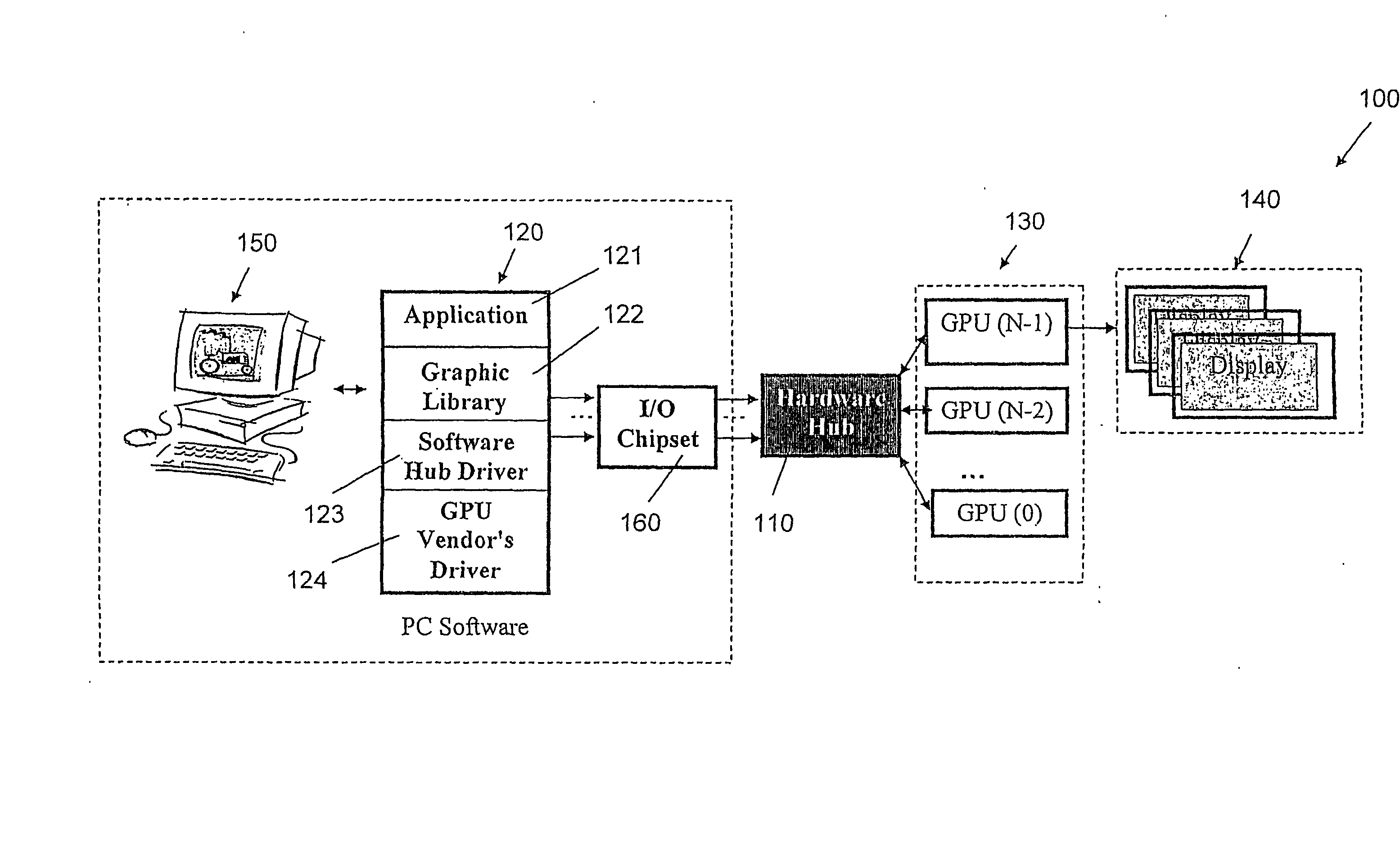
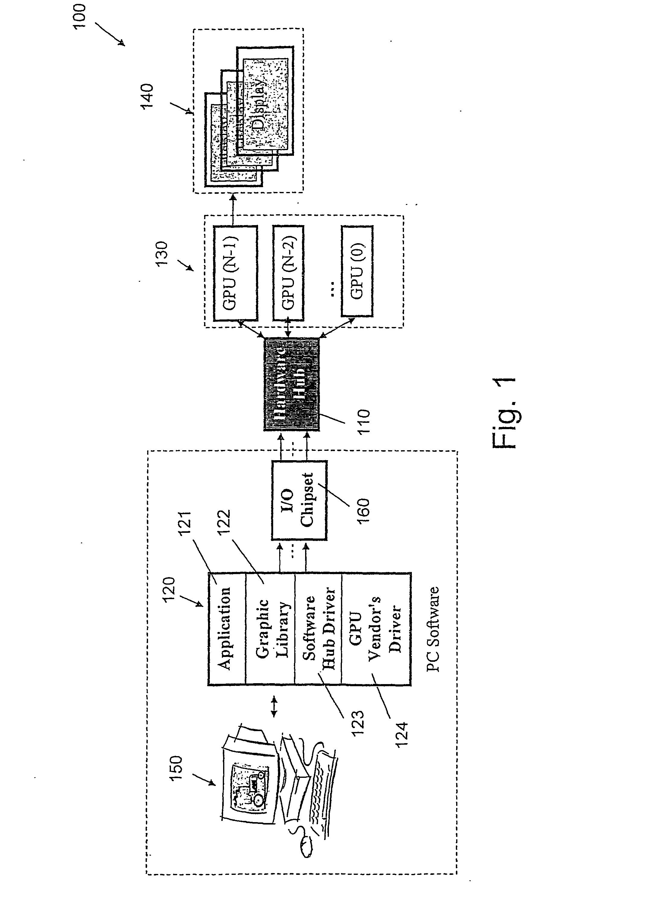
[0079]FIG. 1 presents multiple GPU architecture system 100, according to an embodiment of the present invention. The hub 110 is located in a unique position on the PC bus, between the CPU (Central Processing Unit) and a cluster of GPUs 130. The multiple graphic pipeline architecture, as described in FIG. 1, consists of Software Application 121, Graphic Library 122, Software Hub Driver 123, GPU Driver 124, Hardware Hub 110, cluster of GPUs 130, and display(s) 140. Usually, one of the GPUs is designated as a display unit. It should be noted, that it is possible to have more than one display unit, or include a display unit directly inside the Hardware Hub. A display unit can drive multiple screens, as well.

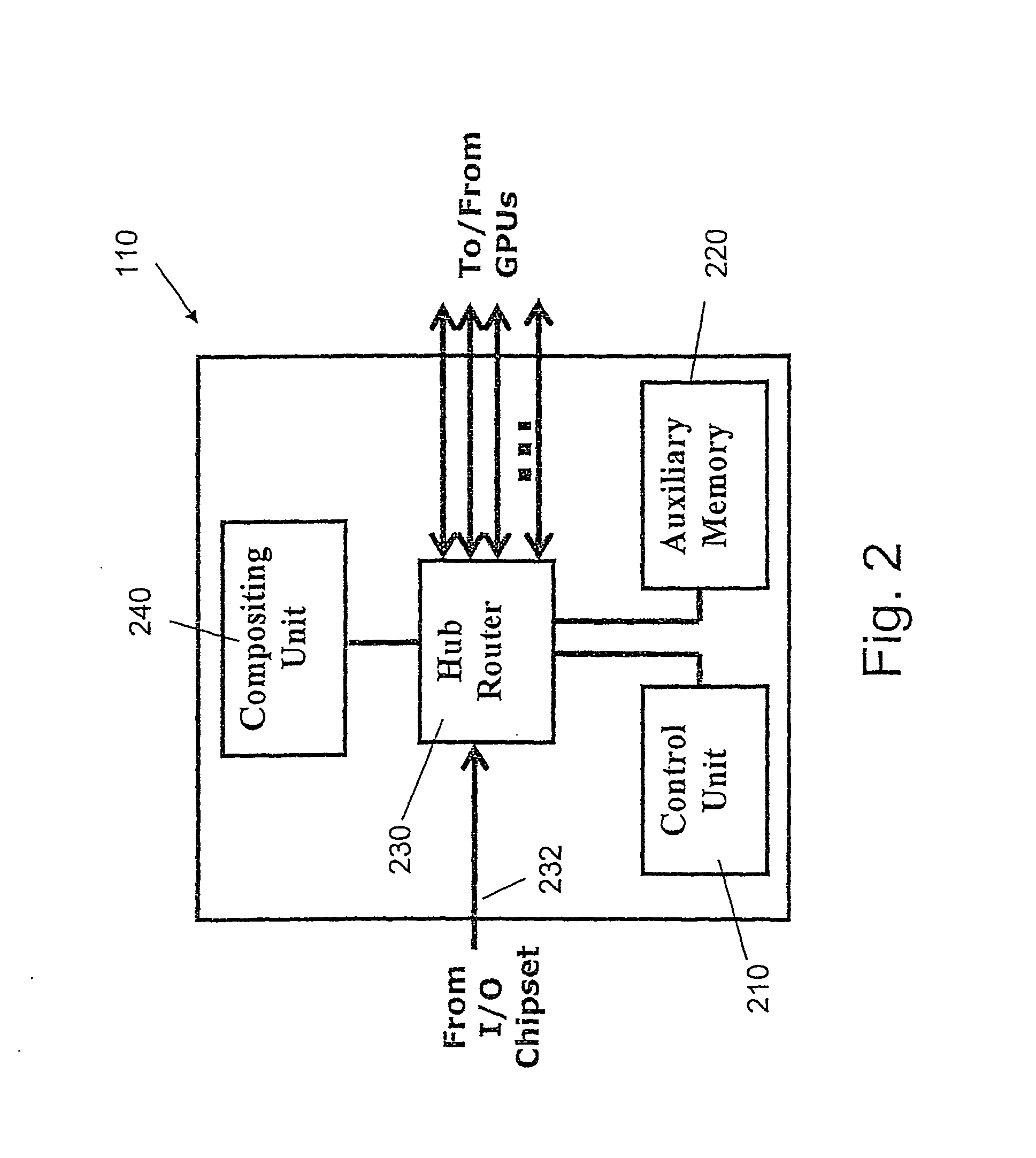
[0080] The Hub mechanism consists of a Hardware Hub component 110, located on the PC b...


PUM


Abstract

Method and system for improving the parallelization of image processing, using one or more parallelization modes, wherein the4 image that is displayed on at least one computer screen by one or more Graphics Processing Units (GPUs) (130). Software applications (121) are provided for issuing graphics command and graphics libraries (122) are provided for storing data used to implement the graphics commands. A Software Hub Drivers (123) is provided for controlling a Hardware Hub (110), for performing real-time analysis of a data stream, from which frames of the image are generated, for determining the parallelization mode of each GPU, and for forwarding the data stream or a portion thereof to each GPU. GPU Drivers (124) are provided for allowing the GPUs to interact with the graphics libraries and an I / O module (160) is provided for interconnecting between the Software module and the Hardware Hub.

Description

FIELD OF THE INVENTION [0001] The present invention relates to a method and system for 3-D (three-dimensional) multiple graphic processing. More particularly, the invention relates to a method and system for improving the parallelization of image processing by Graphic Processing Units (GPUs), based on unified framework of three parallelization methods, which are time division, image division and object division methods. DEFINITIONS, ACRONYMS AND ABBREVIATIONS [0002] Throughout this specification, the following definitions are employed: [0003] GPU: GPU (Graphic Processing Unit) like the CPU (Central Processing Unit), a GPU is a single-chip processor which is used primarily for computing 3-D functions. This includes tasks such as, lighting effects, object transformations, and 3-D motion. These are mathematically-intensive tasks, which otherwise, would put quite a strain on the CPU, but since the specialized GPU can handle most of the 3-D calculations, it helps the computer to perform ...

Claims


Application Information

Patent Timeline
Patent Type & Authority Applications(United States)
IPC IPC(8): G06T15/00G06F15/80G06T
CPCG06F3/14G06F3/1438G06F9/505G09G5/363G06T15/005G06T2200/28G06T1/20
Inventor BAKALASH, REUVENREMEZ, OFFIRBAR-OR, GIGYFOGEL, EFISHAHAM, AMIR
Owner GOOGLE LLC
Learn More