
Cold Idle Adaptive Air-Fuel Ratio Control Utilizing Lost Fuel Approximation

Inactive Publication Date: 2007-12-06
FORD GLOBAL TECH LLC
View PDF23 Cites 7 Cited by
  • Summary
  • Abstract
  • Description
  • Claims
  • Application Information

AI Technical Summary

Benefits of technology

[0006]In this way, it is possible to utilize feedback information to obtain a more accurate determination of appropriate fueling during cold start open-loop conditions, thereby better accounting for variations in lost fuel. For example, as the engine ages, lost fuel can vary, thereby leading to increased emissions if not otherwise corrected.
[0007]In one particular aspect, by using cycle average information of first complete fueling cycle, it is possible to obtain ever more accurate fueling corrections. In another aspect, the fueling adjustment is provided only under select conditions to avoid inaccurate readings that may be caused by various conditions.

Problems solved by technology

Engine starting during cold operating conditions, referred to as a “cold start”, can present numerous challenges in maintaining repeatability / reliability and meeting emission requirements.
Specifically, providing appropriate engine air-fuel ratio during engine starting conditions can be difficult due to numerous factors, especially given that exhaust gas oxygen sensors used for feedback air-fuel control are typically unavailable during the initial operation of a cold start.
One phenomenon that can degrade cold start air-fuel ratio control is when a portion of injected fuel may not be available for combustion due to fuel vaporization.
Further, lost fuel can significantly impact open-loop fueling precision and accuracy, and cause the observed open-loop air-fuel ratio to deviate from the desired target value.
However, the inventors herein have recognized a disadvantage with such an approach.
In particular, the amount of correction at the exact moment of sensor activation may not accurately reflect the open-loop fueling error caused by lost fuel effects.
Further, depending on the type of exhaust gas oxygen sensor provided, it may not be possible to identify how much error is present at the exact moment of sensor activation.
For example, as the engine ages, lost fuel can vary, thereby leading to increased emissions if not otherwise corrected.

Method used


Image

  • Cold Idle Adaptive Air-Fuel Ratio Control Utilizing Lost Fuel Approximation
  • Cold Idle Adaptive Air-Fuel Ratio Control Utilizing Lost Fuel Approximation
  • Cold Idle Adaptive Air-Fuel Ratio Control Utilizing Lost Fuel Approximation

Examples


Embodiment Construction

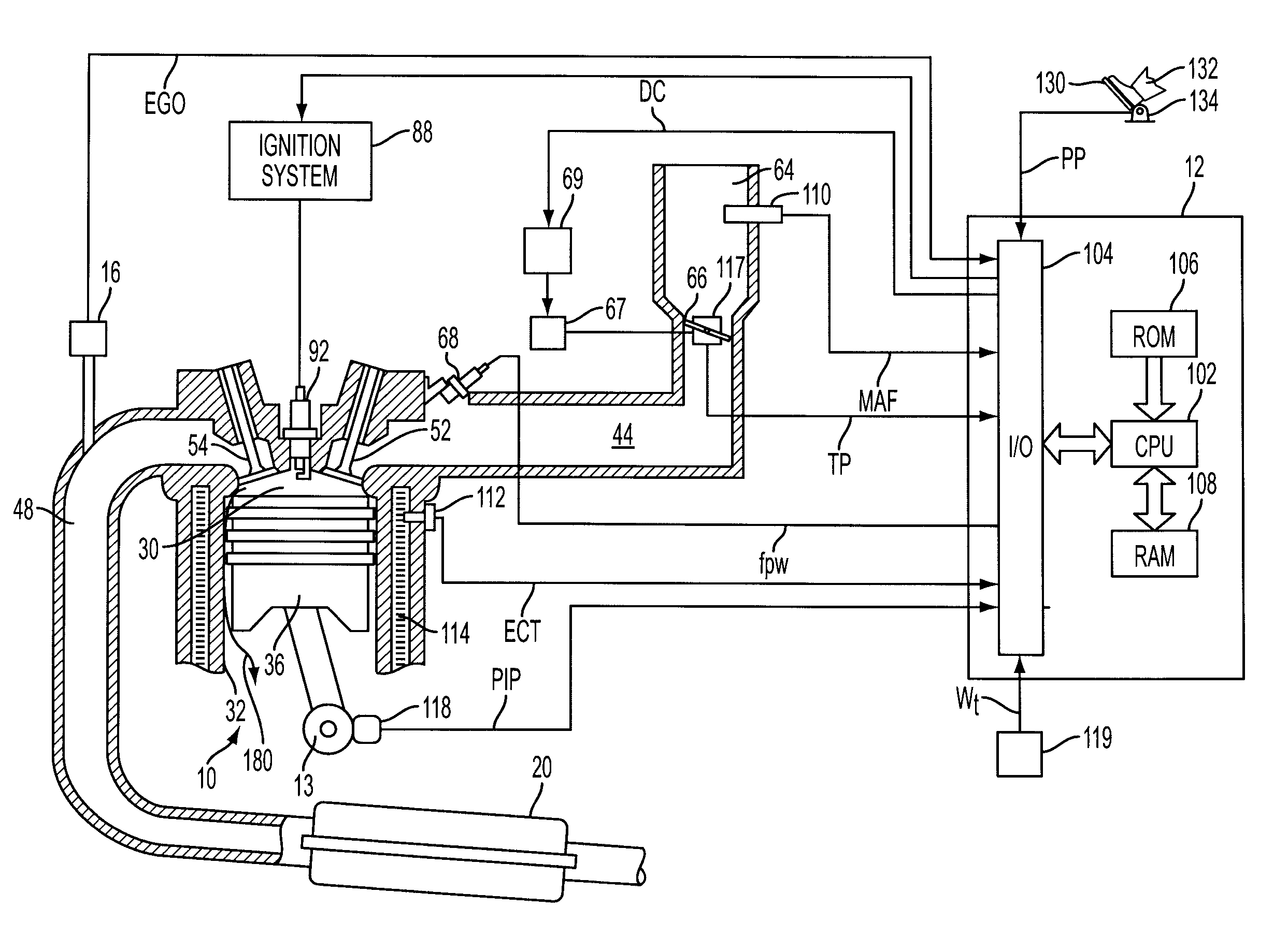
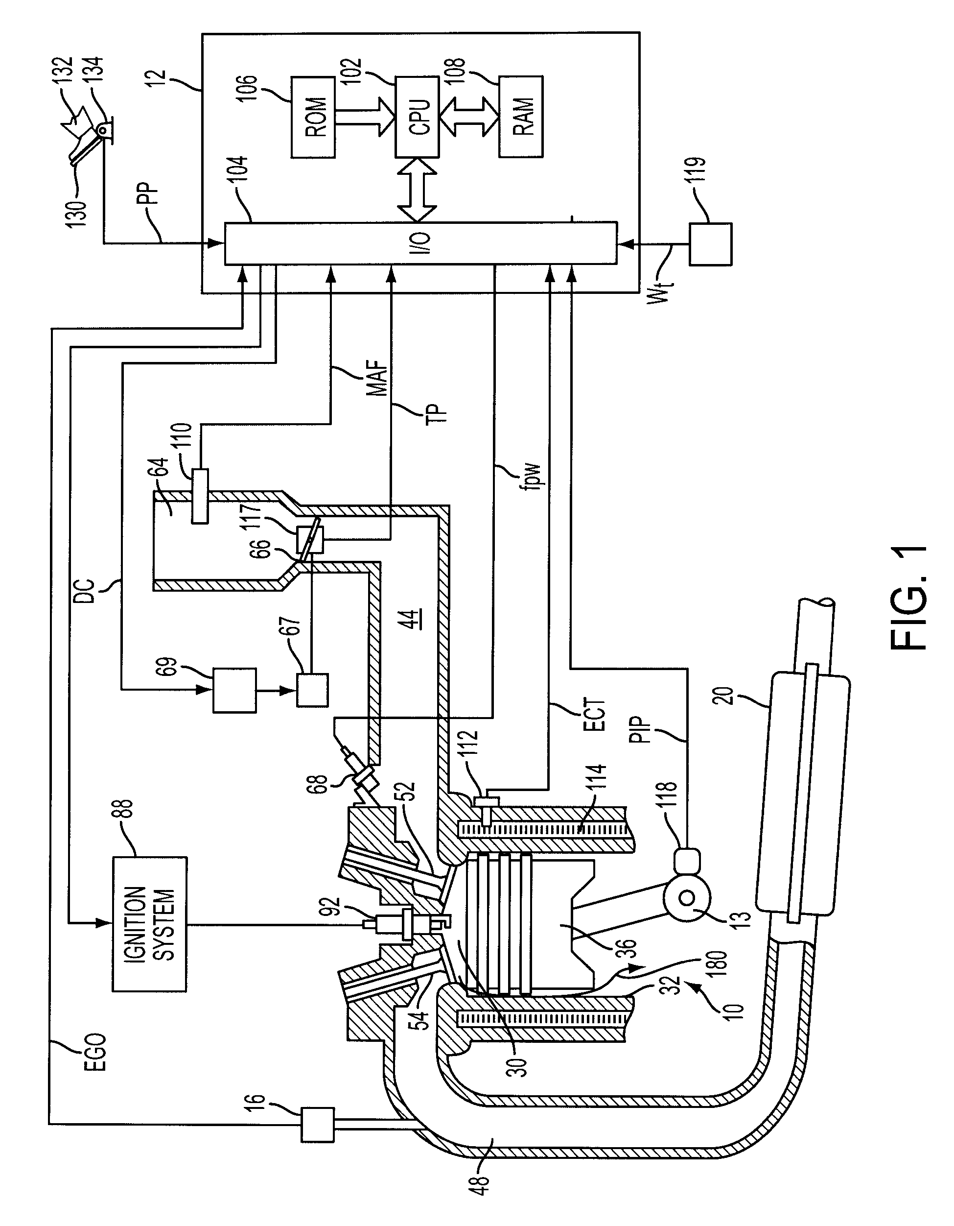
[0013]Internal combustion engine 10 comprising a plurality of cylinders, one cylinder of which is shown in FIG. 1, is controlled by electronic engine controller 12. Engine 10 includes combustion chamber 30 and cylinder walls 32 with piston 36 positioned therein and connected to crankshaft 13. Combustion chamber 30 communicates with intake manifold 44 and exhaust manifold 48 via respective intake valve 52 and exhaust valve 54. Exhaust gas oxygen sensor 16 is coupled to exhaust manifold 48 of engine 10 upstream of catalytic converter 20.

[0014]Intake manifold 44 communicates with throttle body 64 via throttle plate 66. Throttle plate 66 is controlled by electric motor 67, which receives a signal from ETC driver 69. ETC driver 69 receives control signal (DC) from controller 12. Intake manifold 44 is also shown having fuel injector 68 coupled thereto for delivering fuel in proportion to the pulse width of signal (fpw) from controller 12. Fuel is delivered to fuel injector 68 by a convent...


PUM


Abstract

A method for controlling fueling of an engine, the method comprising during an engine cold start and before the engine is warmed to a predetermined level, transitioning from open-loop fueling to closed-loop fueling, where during closed-loop fueling feedback from an exhaust gas oxygen sensor is utilized and where said closed-loop fueling generates a cycling of delivered fuel in maintaining exhaust air-fuel ratio at a desired level; and providing a fueling adjustment to a subsequent engine start in response to fueling information, said fueling information obtained over at least a complete cycle of closed-loop fueling following said transition from open-loop fueling.

Description

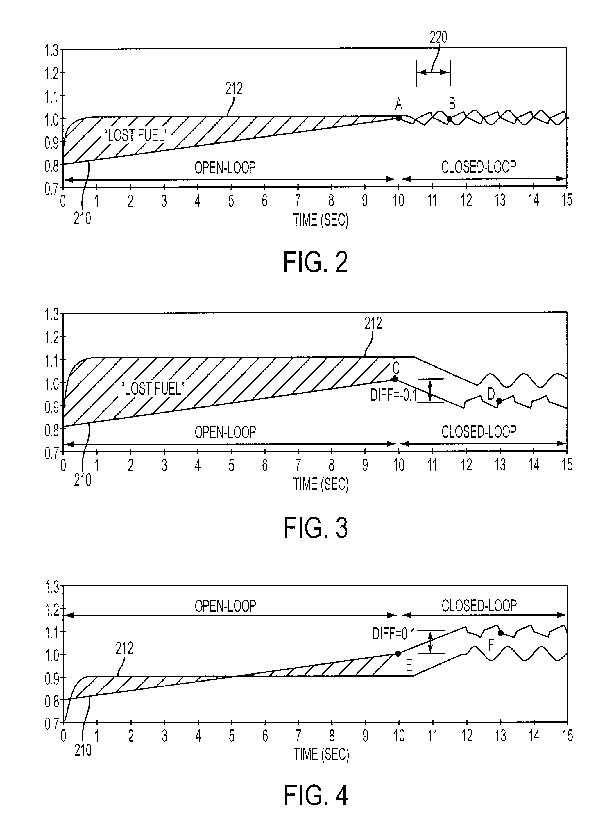
BACKGROUND AND SUMMARY[0001]Engine starting during cold operating conditions, referred to as a “cold start”, can present numerous challenges in maintaining repeatability / reliability and meeting emission requirements. Specifically, providing appropriate engine air-fuel ratio during engine starting conditions can be difficult due to numerous factors, especially given that exhaust gas oxygen sensors used for feedback air-fuel control are typically unavailable during the initial operation of a cold start. As such, the initial fueling may be referred to as open-loop air-fuel control.[0002]One phenomenon that can degrade cold start air-fuel ratio control is when a portion of injected fuel may not be available for combustion due to fuel vaporization. This phenomenon may be referred to as “lost fuel” and can be significantly influenced by intake port surface temperature at start-up and fuel volatility (vapor pressure and distillation properties). Further, lost fuel can significantly impact ...

Claims


Application Information

Patent Timeline
IPC IPC(8): F02M51/00G06G7/70G06F19/00
CPCF02D41/062F02D41/2454F02D41/2441F02D41/1488
Inventor HUSAK, PHILIPMEYER, DANIELNALLAPERUMAL, VENKATESWARANCULLEN, MICHAEL J.ROTH, PAULSMOKOVITZ, MICHAEL
Owner FORD GLOBAL TECH LLC
Learn More