Dental Radiology Apparatus and Signal Processing Method Used Therewith

a radiology apparatus and signal processing technology, applied in the field of dental radiology, can solve the problems of deteriorating signal-to-noise ratio, hindering obtaining good signal-to-noise ratio, and cmos detectors obtaining a signal-to-noise ratio of inferior quality to that of ccd detectors, so as to reduce the risk of pollution of cmos signals during transmission, not deteriorating the detector's signal-to-noise ratio

Active Publication Date: 2007-11-29
CARESTREAM DENTAL TECH TOPCO LTD
View PDF13 Cites 2 Cited by
  • Summary
  • Abstract
  • Description
  • Claims
  • Application Information

AI Technical Summary

Benefits of technology

[0079] By integrating the sequencer on the same silicon chip as the array and not in offset electronic equipment, a reduced number of electrical signals is required to operate the sequencer and the array and that have to be received from outside the sensor, which is particularly advantageous because there are thus fewer external signals to be produced.
[0080] This therefore enables the risks

Problems solved by technology

It can be observed that the CMOS detector obtains a signal-to-noise ratio (SNR) of inferior quality to that of the CCD detector.
The presence of the dark current leads to a deterioration of the signal-to-noise ratio.
With part of the pixel not contributing to the fill, i.e. not contributing to the photon-electron conversion, the fill factor is less than 1, which hinders obtaining a good signal-to-noise ratio.
A third limiting factor results from the fact that today we do not know how to use CMOS technology to make large size monolithic active pixel arrays, typically about 20×30 mm, which are the commonly used dimensions for dental radiology sensors.
The unevenness created by an array obtained in this way contributes to deteriorating the signal-to-noise ratio.
Further, it should be noted that the conditions specific to the field of dental radiology make the design of dental radiology apparatus with a high quality signal-to-noise ratio particularly difficult.
Detector design like this goes against the miniaturization required for installation in a patient's mouth.
In addition, the introduction of an analog-digital converter along

Method used


Image

  • Dental Radiology Apparatus and Signal Processing Method Used Therewith
  • Dental Radiology Apparatus and Signal Processing Method Used Therewith
  • Dental Radiology Apparatus and Signal Processing Method Used Therewith

Examples


Embodiment Construction

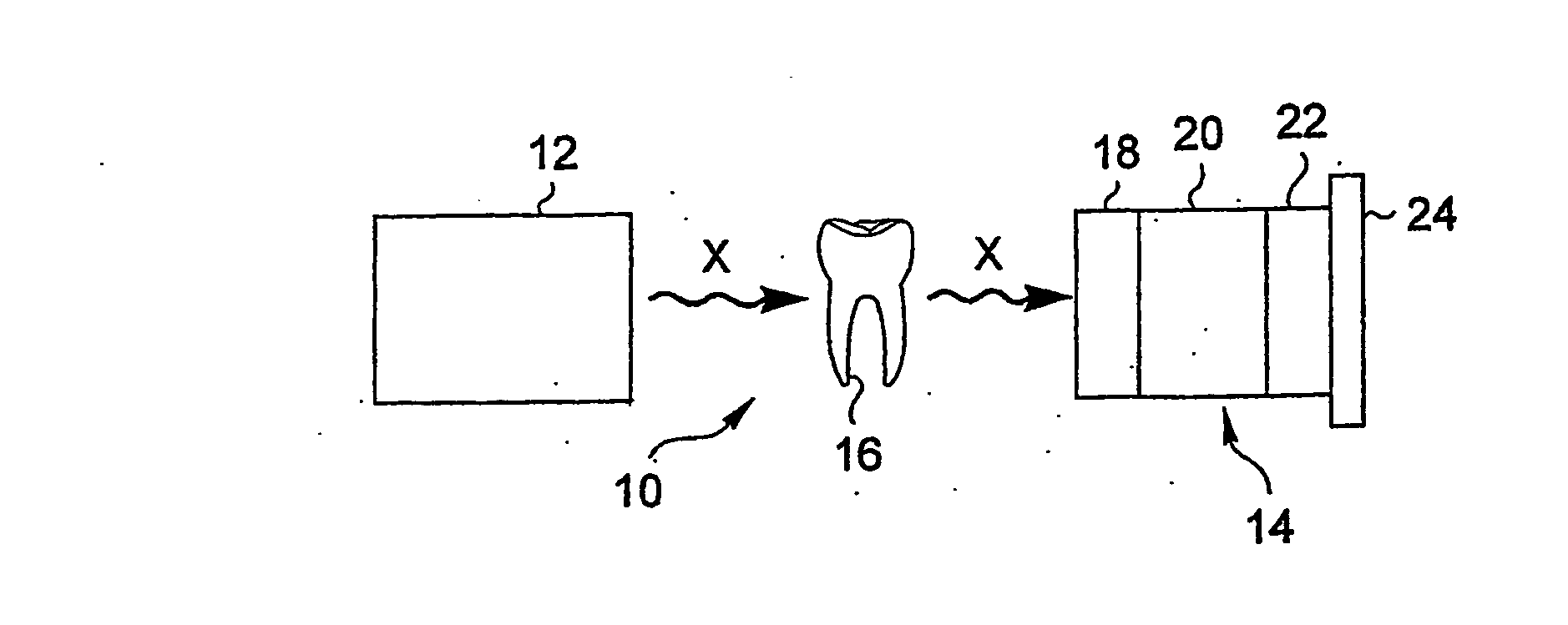
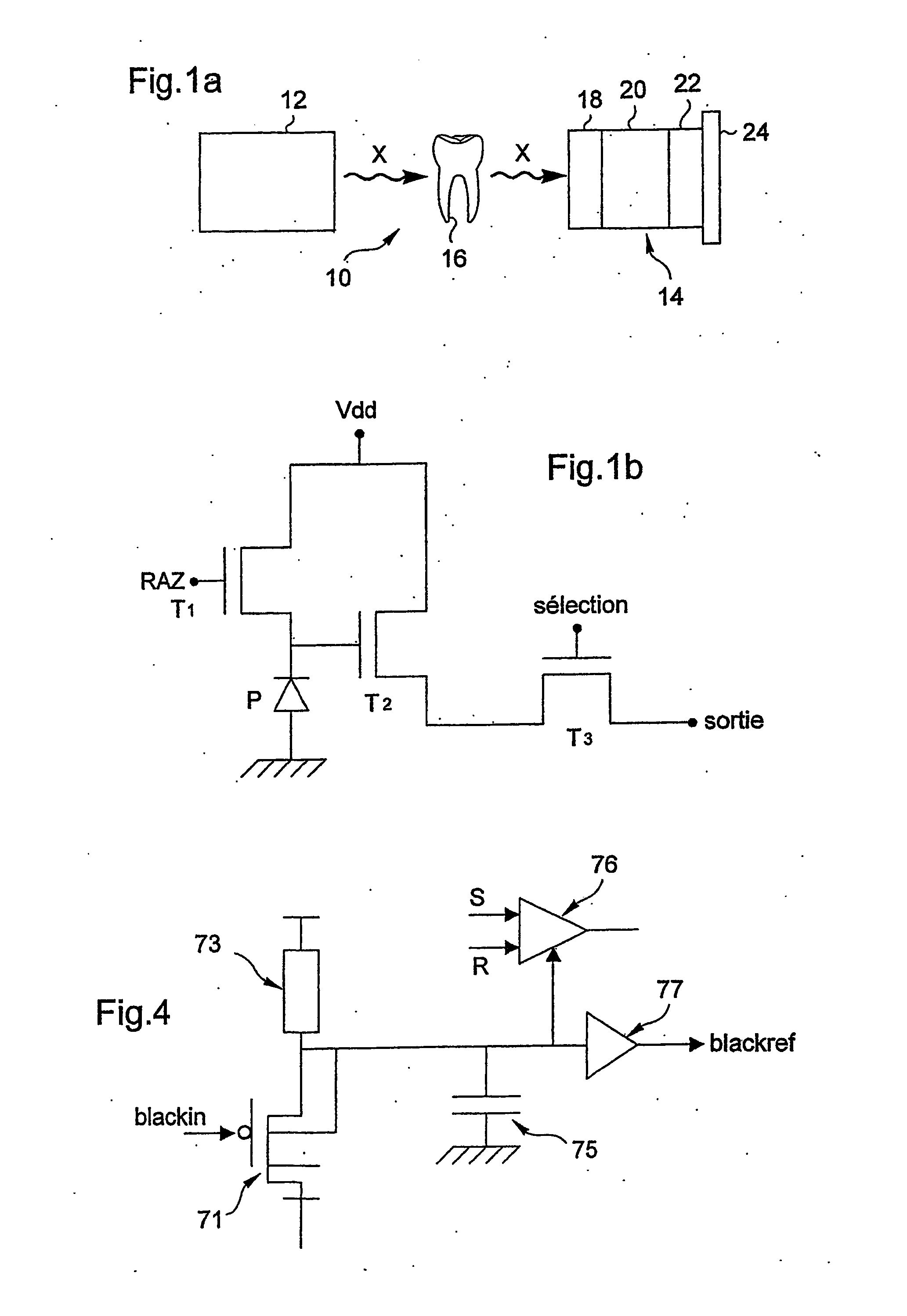
[0218] As represented in FIG. 1a , an x-ray dental radiology apparatus 10 comprises an x-ray source 12 placed outside a patient's mouth and an intraoral radiation sensor 14 placed in a patient's mouth, behind a tooth 16, and which is capable of receiving the x-rays that have passed through the tooth.

[0219] The sensor 14 comprises, in the propagation order of the radiation, a scintillator 18 that converts the x-rays that have passed through the tooth into visible light, a fiber optic plate 20 that, on the one hand, includes metal particles intended to absorb the part of the x-rays received by the scintillator and not converted into visible light and, on the other hand, conducts the visible light thus converted to a detector 22. This detector is mounted on a ceramic substrate 24 and converts the visible light from the glass fibers into one or more analog electrical signals.

[0220] The various components of the sensor 14 are assembled together, for example, by gluing.

[0221] The scint...


PUM


Abstract

The invention relates to a dental radiology apparatus, characterized in that it comprises: an intraoral sensor comprising a detector that includes an active pixel array produced using biCMOS technology and converting a received x-ray into at least one analog electrical output signal, an electronic module encapsulated in a case and which has at least one detector activation device, the module being linked to the sensor by a wire link for the transmission to said sensor of a detector activation signal generated in the module and for the transmission to the module of said at least one analog electrical output signal, the module having analog-digital means for converting said at least one analog electrical output signal into at least one digital output signal, a remote processing and display unit of said at least one digital output signal which is linked to the electronic module by a wire link intended to ensure the transmission to the unit of said at least one digital output signal.

Description

FIELD OF THE INVENTION [0001] The invention relates to the field of dental radiology. BACKGROUND OF THE INVENTION [0002] Dental radiology equipment as described in French patent FR 2,547,495 and European patent No. 0,129,451 is known. [0003] Such equipment comprises an x-ray source that emits radiation directed to a tooth located in a patient's mouth and behind which is an intraoral sensor that receives the x-rays that have passed through the tooth. [0004] This sensor comprises: [0005] a scintillator on entry to convert the x-rays that have passed through the tooth into visible light, [0006] a fiber optic plate to transmit the converted visible light to a charge-coupled device CCD-type detector, which converts the converted visible light into an analog electrical signal, while absorbing the residual x-rays that have not been converted into visible light. [0007] The electrical signal is amplified and transmitted in analog form through a long cable, to a remote processing and display ...

Claims


Application Information

Patent Timeline
IPC IPC(8): A61B6/14G01N23/04H04N5/225H04N5/32
CPCA61B6/145A61B6/4233G01N23/04A61B6/548H04N5/378H04N2005/2255A61B6/4423H04N5/32H04N23/555H04N25/75
Inventor BOUCLY, ALAININGLESE, JEAN-MARCCONGY, PHILIPPE
Owner CARESTREAM DENTAL TECH TOPCO LTD
Why Eureka
Try Eureka