
Electrically Controllable Color Conversion Cell

a color conversion cell and electric control technology, applied in the field of diodes light sources, can solve the problems of difficult to perform the simple task of dimming a light source without changing its color, and the relative intensities of giving a desired color will change, so as to increase the intensity of source light incident, the effect of improving the efficiency of color conversion

Inactive Publication Date: 2007-11-29
SIGNIFY HLDG BV
View PDF10 Cites 53 Cited by
  • Summary
  • Abstract
  • Description
  • Claims
  • Application Information

AI Technical Summary

Benefits of technology

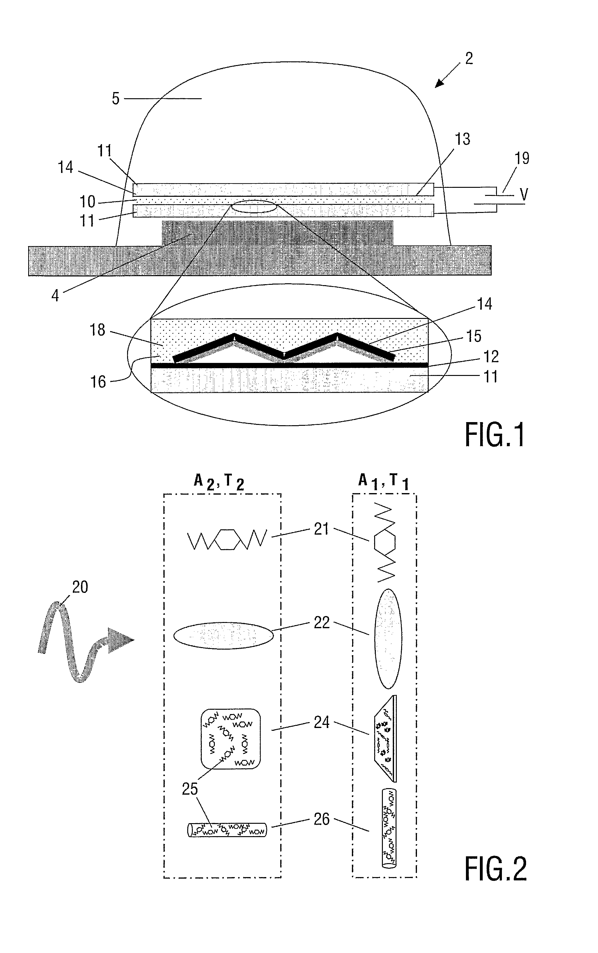
[0021] The color conversion cell may be shifted between the first and second state by adjusting one or more of the parameters mentioned above. The first ratio, Ax, is an absorption coefficient defined as the quotient between absorbed light and incident light in the state X. It follows that 0≦Ax≦1. Similarly, second ratio, Tx, is a transmission coefficient defined as the quotient between transmitted light and incident light in the state X. It also follows that 0≦Tx≦1. Preferably, the one or more parameters may be adjusted continuously to allow for a smooth transition between two color states. It is thus evident that the first and second ratios may take several values in between their values in the first and second state.
[0026] In another alternative, the anisometric particles need not be fluorescent dyes themselves, but can have color converting substance attached to their surfaces. As the amount of light incident on the particle surface, and thereby on the color converting substance, depends on the alignment of the alignment. Here, the color converting substance itself may be isometric, which allows for a much larger selection of substances.
[0030] In still another preferred embodiment, the color conversion cell is adapted to adjust an average pathlength of the source light in the matrix containing the color converting substance inside the cell. If the average pathlength of the source light is longer in the first state of the cell than in the second state, more light will be absorbed and re-emitted in the first state, resulting on a larger color conversion. The pathlength may be adjusted by scattering the source light in the matrix, with an increased scattering leading to a longer pathlength. To this point, the color conversion cell preferably comprises electrically controllable scattering media such as polymer dispersed liquid crystal or liquid crystal gel or chiral texture. This embodiment have the advantage that the color converting substance need not be dichroic or anisometric, thus providing a larger selection of applicable substances. However the effect may be increased when anisometric particles or dichroic molecules are used.
[0036] The efficiency of the color conversion can be improved by increasing the intensity of source light incident on the cell. For this purpose, the light emitting device may further comprise a layer with a collimating micro structure such as a lens or a grating positioned between the light source and the color conversion cell.
[0043] adjusting a voltage between the two electrodes to increase or decrease the amount of source light absorbed by the color converting substance and the amount of light with a second emission spectrum emitted by the color converting substance.

Problems solved by technology

This approach has the drawback that diodes emitting different colors age in different ways, so that the relative intensities giving a desired color will change over time.
It is a disadvantage of the light source described in U.S. Pat. No. 6,375,889, that it is the emission intensity of the diodes, which is used to control the color.
Firstly, for a given color of the light source, the diodes that contribute only little to this color must emit at a very low intensity—even though the light source as a whole emits the color at its highest intensity.
Secondly, the color converting phosphors respond differently to the different emission spectra of the diodes.
This makes it difficult to perform the simple task of dimming a light source without changing its color.

Method used


Image

  • Electrically Controllable Color Conversion Cell
  • Electrically Controllable Color Conversion Cell
  • Electrically Controllable Color Conversion Cell

Examples


Embodiment Construction

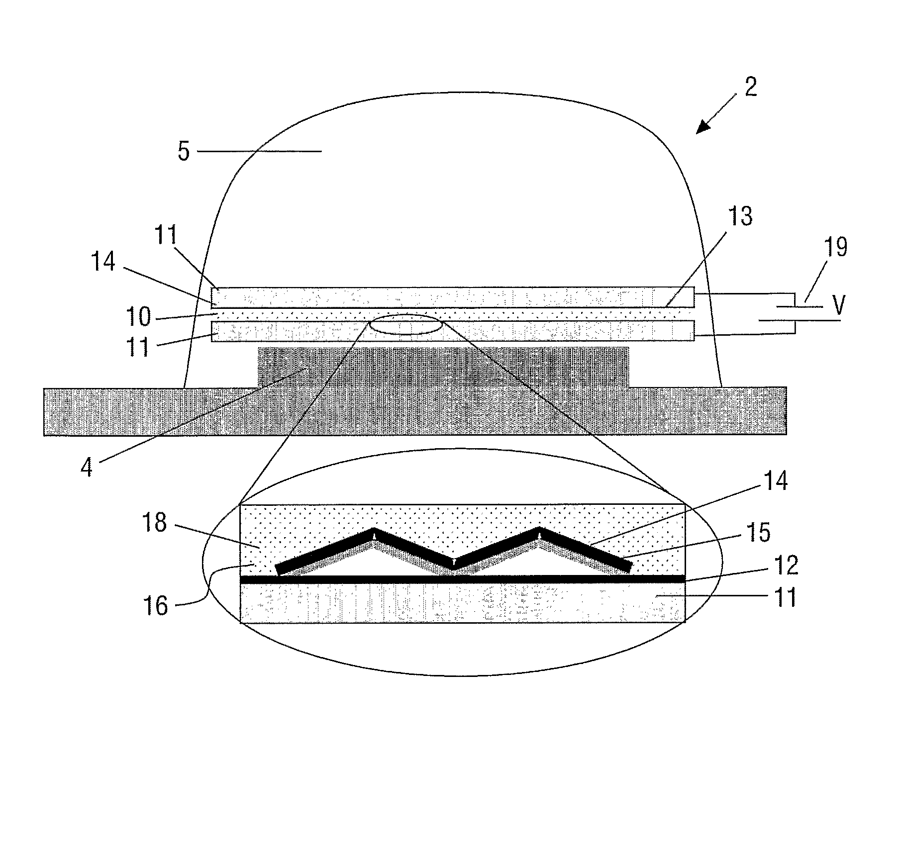
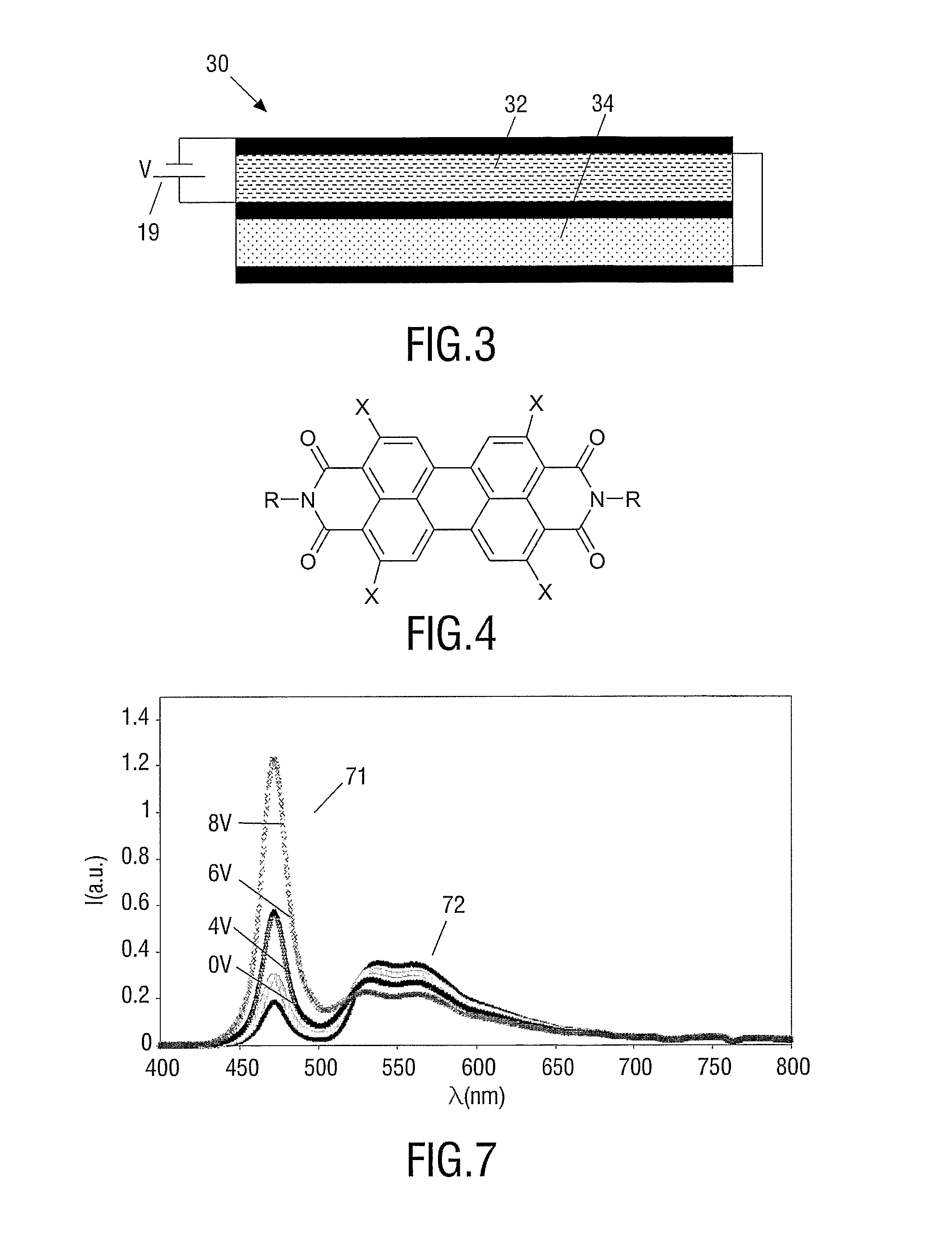
[0060] The following description proposes several light emitting devices for performing electrically controllable color conversion based on adjustable absorption and reemission by a color converting substance, typically a fluorescent dye. FIG. 1 illustrates a typical layout of such light emitting device. The designs presented in the present description primarily serves to illustrate the working principle of the invention and its embodiments, and secondly to present ways for carrying out the invention. These designs are not intended to restrict the scope of the invention in any way.

[0061] In FIG. 1, a light emitting device 2 comprises an LED light source 4 and a color conversion cell 10, all encapsulated in a lens 5. The cell 10 has transparent glass walls 11 with transparent electrodes 12 and 13 and a reflector 15 at the wall nearest the LED. The cell contains a color converting substance 18 mixed in a liquid matrix 16. The orientation of either the constituents of the matrix 16, t...


PUM

PropertyMeasurementUnit
thicknessaaaaaaaaaa
diameteraaaaaaaaaa
thicknessaaaaaaaaaa

Abstract

The invention relates to light emitting devices (2) with variable output color. More specifically, the inventions provides a color conversion cell (10) which can be positioned in front of a light source (4) in order to generate other color or color temperatures. Typically the light source is a light emitting diode (LED) which is power efficient but emits in a narrow and fixed spectra. The new colors are generated by photoluminescence in fluorescent dyes contained in the cell. The color converting of the cell is electrically controllable, preferably by controlling the orientation, density or distribution of the fluorescent dyes, or by controlling a pathlength of the light in the cell.

Description

FIELD OF THE INVENTION [0001] The invention relates to diode light sources with variable output color. BACKGROUND OF THE INVENTION [0002] Methods for varying the color of a light source can be divided into two cases, passive color conversion where filters etc. remove some frequencies to change the color, and active color conversion where fluorescent or phosphorescent substances alters the spectrum of the light from the light source by absorption and re-emission. Active color conversion has the advantages that it maintains the light power to a higher degree than passive color conversion. Further, active color conversion can produce wavelengths not contained in, or increase emission at wavelengths only weakly represented in, the emission spectrum of the light source. For this reason, active color converting substances are preferred for adjusting colors and color temperatures. [0003] Light emitting diodes (LED's) are considered to become the next generation of lighting sources. Highly ...

Claims


Application Information

Patent Timeline
Patent Type & Authority Applications(United States)
IPC IPC(8): H01J1/62C09K11/06C09K11/08G02F1/13G02F1/23H01L33/50
CPCC09K11/02C09K11/06C09K11/08F21V14/003F21Y2101/02G02F1/23H01L33/50H01L33/502G02F1/13762F21Y2115/10
Inventor HIKMET, RIFAT ATA MUSTAFA
Owner SIGNIFY HLDG BV
Learn More