Ultra low NOx burner replacement system

a burner replacement and ultra low technology, applied in the field of ultra low nox burner replacement system, can solve the problems of not being particularly adapted to reduce the nosub>x/sub>(nitrogen oxide) byproducts of the burner replacement system, conventional combustion boilers, etc., to facilitate the redistribution of fuel flow, and facilitate the reduction of an amount of nitrous oxide

Inactive Publication Date: 2007-11-29
FUEL TECH
View PDF25 Cites 13 Cited by
  • Summary
  • Abstract
  • Description
  • Claims
  • Application Information

AI Technical Summary

Benefits of technology

[0010]The present invention also relates to a replacement burner system which facilitates reduction in an amount of nitrous oxide produced during combustion of a fuel, the replacement burner system comprising: a fuel supply duct having an inlet and an outlet and a bend located between the inlet and the outlet; a fuel deflector located within the fuel supply duct, between the bend and the outlet, to facilitate redistribution of a flow of the fuel; a coal nozzle located within the fuel supply duct between the fuel deflector and the outlet, the coal nozzle facilitates supplying two distinct coal flow zones, and a position of the coal nozzle being adjustable along a length of the fuel supply duct; and an exterior surface of the fuel supply duct supporting an air swirling device, and the air swirling device swirling between about 30% and about 50% of the combustion air flowing between an exterior surface of the fuel supply duct and the inwardly facing surface of the venturi register, after the replacement burner system is accommodated within a windbox of a combustion boiler, and the air swirling device facilitates supplying three distinct air flow zones.
[0011]The present invention also relates to a replacement burner system which facilitates reduction in an amount of nitrous oxide produced during combustion of a fuel, the replacement burner system comprising: a fuel supply duct having an inlet and an outlet with a bend located between the inlet and the outlet; a fuel deflector located within the fuel supply duct, between the bend and the outlet, to facilitate redistribution of a flow of the fuel flowing through the fuel supply duct; a coal nozzle located within the fuel supply duct between the fuel deflector and the outlet, and a position of the coal nozzle being adjustable along a length of the fuel supply duct; an exterior surface of the fuel supply duct supporting an air swirling device, and the air swirling device swirling between about 30% and about 50% of the combustion air flowing between an exterior surface of the fuel supply duct and the inwardly facing surface of the venturi register, after the replacement burner system is accommodated within the windbox of a combustion boiler; and only the air swirling device is located in the windbox, between the exterior surface of the fuel supply valve and the inwardly facing surface of the venturi register, to facilitate adjustment of a flow of the combustion air flowing through the venturi register.

Problems solved by technology

During operation of conventional boilers, normal wear and tear causes the burner, of a conventional combustion boiler, to periodically require servicing or, in some instances, be completely replaced.
While a variety of known burner replacement burners and systems are currently available on the market, many of the burner replacement systems are not particularly adapted for reducing the NOx (nitrogen oxides) byproducts which result from combustion of a fuel, such as coal.

Method used


Image

  • Ultra low NOx burner replacement system
  • Ultra low NOx burner replacement system
  • Ultra low NOx burner replacement system

Examples


Embodiment Construction

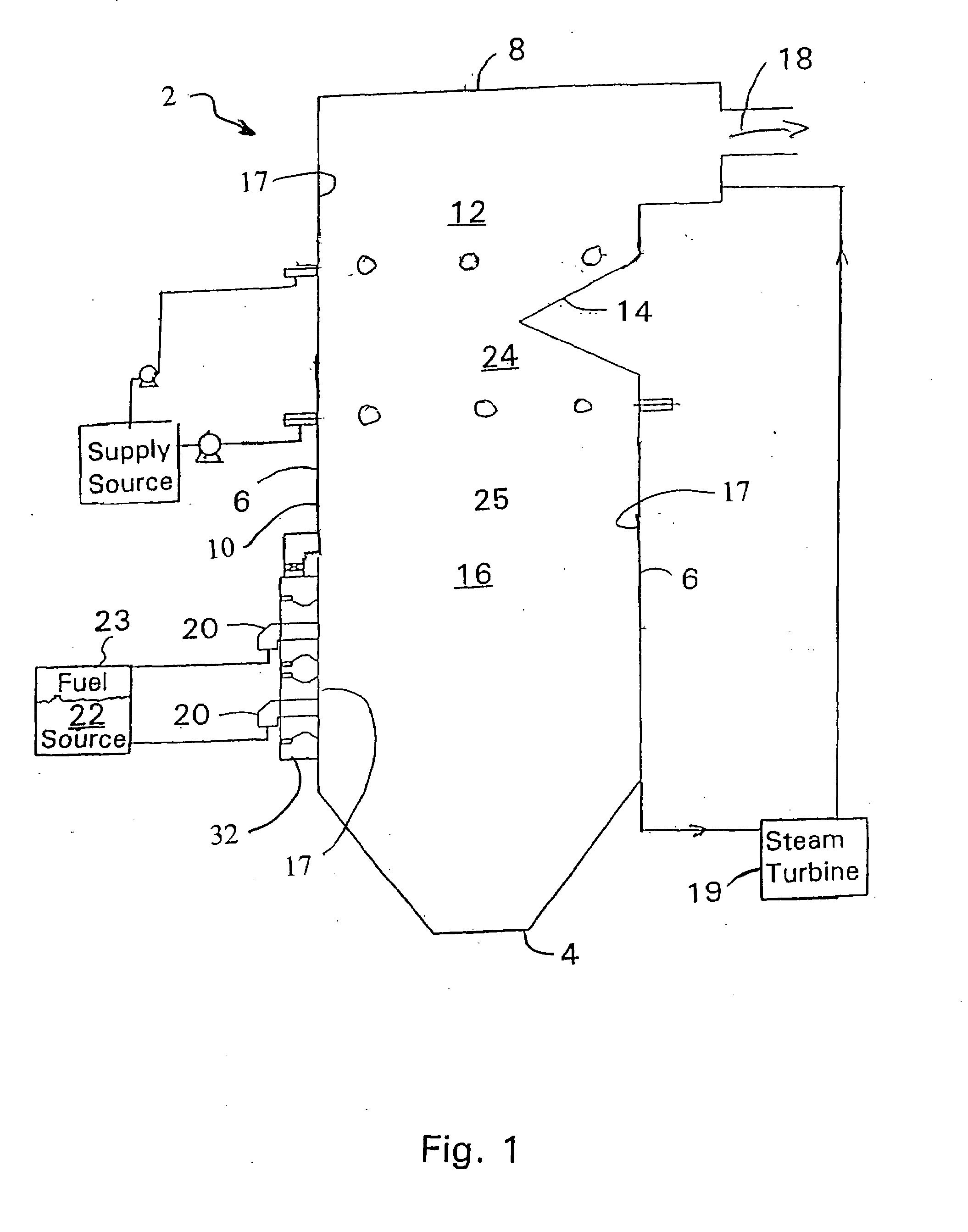
[0024]Turning now to the FIG. 1, a brief description concerning the general components of a combustion boiler will first be described and this will be followed by a detailed description of the present invention. As can be seen in FIG. 1, the combustion boiler is generally designated with reference numeral number 2. The combustion boiler 2 includes a base wall 4 and a sidewall 6, e.g., generally four sidewalls, as well as a top wall 8. The base wall 4, the four sidewalls 6 and the top wall 8 define an enclosed area or exterior housing 10 which forms the combustion boiler 2. An inwardly tapering indentation 14 is formed in the rear sidewall 6 of the housing 10 and this inwardly tapering indentation 14 forms a constriction or a throat in the combustion boiler 2 that accelerates the combustion byproducts as they flow from a vertically lower primary combustion chamber 16 into a vertically higher secondary combustion chamber 12. Finally, an exit section 18 is formed in one of the sidewall...


PUM


Abstract

A replacement burner system which facilitates reduction of nitrous oxide produced during combustion of a fuel. The replacement burner system comprising a fuel supply duct having an inlet and an outlet with a fuel deflector located within the fuel supply duct to facilitate redistribution of a flow of the fuel. An adjustable coal nozzle is located within the fuel supply duct between the fuel deflector and the outlet. An exterior surface of the fuel supply duct supports an air swirling device, and the air swirling device obstructs between 65% and 75% of the transverse flow area, located between an exterior surface of the fuel supply duct and the inwardly facing surface of the venturi register, after the replacement burner system is accommodated within the windbox of a combustion boiler. The air swirling device is the only component located in the windbox, between the exterior surface of the fuel supply valve and the inwardly facing surface of the venturi register, for adjusting the flow of the combustion air flowing through the venturi register.

Description

FIELD OF THE INVENTION[0001]The present invention relates to an ultra low NOx burner replacement system used to replace an existing burner of a combustion boiler.BACKGROUND OF THE INVENTION[0002]During operation of conventional boilers, normal wear and tear causes the burner, of a conventional combustion boiler, to periodically require servicing or, in some instances, be completely replaced. While a variety of known burner replacement burners and systems are currently available on the market, many of the burner replacement systems are not particularly adapted for reducing the NOx (nitrogen oxides) byproducts which result from combustion of a fuel, such as coal.[0003]As is well known in the prior art, a reducing agent may be added to the combustion boiler, prior to the combustion byproducts exhausting from the combustion boiler, in order to reduce the amount of NOx remaining in the exhaust stream as the exhaust stream exits from the combustion boiler. The reducing agent is generally ...

Claims


Application Information

Patent Timeline
Patent Type & Authority Applications(United States)
IPC IPC(8): F23C1/04F23D1/00
CPCF23D2201/20F23D1/02
Inventor MARX, PETER D.PICKERING, ROBERT W.TRIPPEL, CHARLES E.
Owner FUEL TECH
Why Eureka
Try Eureka