
Actuating member and method for producing the same

a technology of actuating members and cylinders, which is applied in the direction of ligaments, generators/motors, coatings, etc., can solve the problems of limiting the dynamism of the actuating member, and achieve the effect of small thickness

Inactive Publication Date: 2007-11-22
DANFOSS AS
View PDF99 Cites 19 Cited by
  • Summary
  • Abstract
  • Description
  • Claims
  • Application Information

AI Technical Summary

Benefits of technology

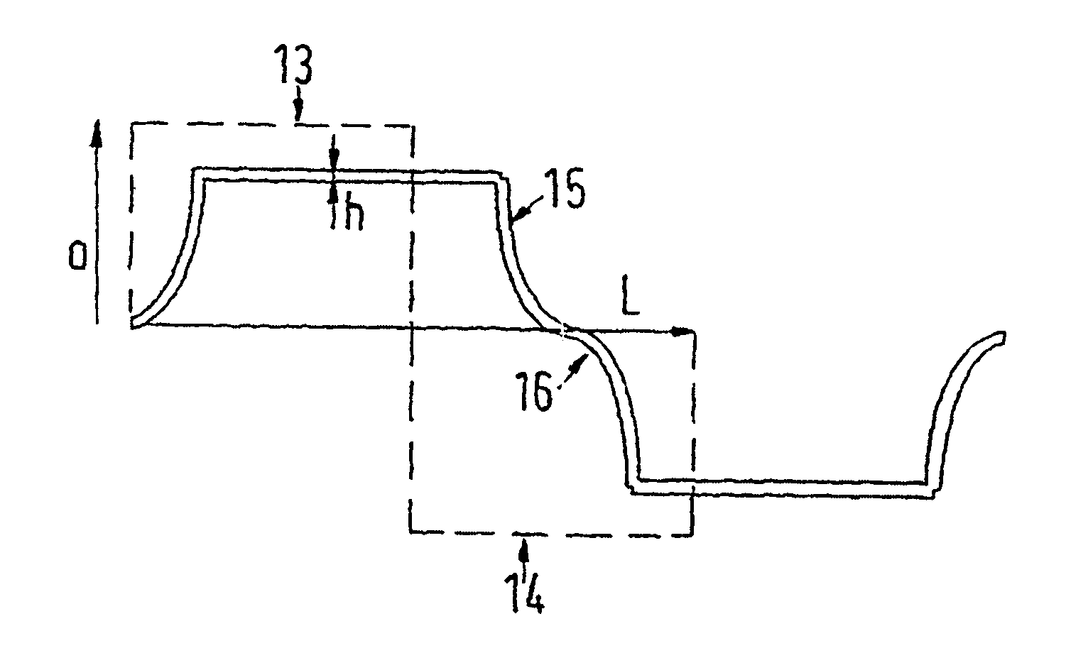
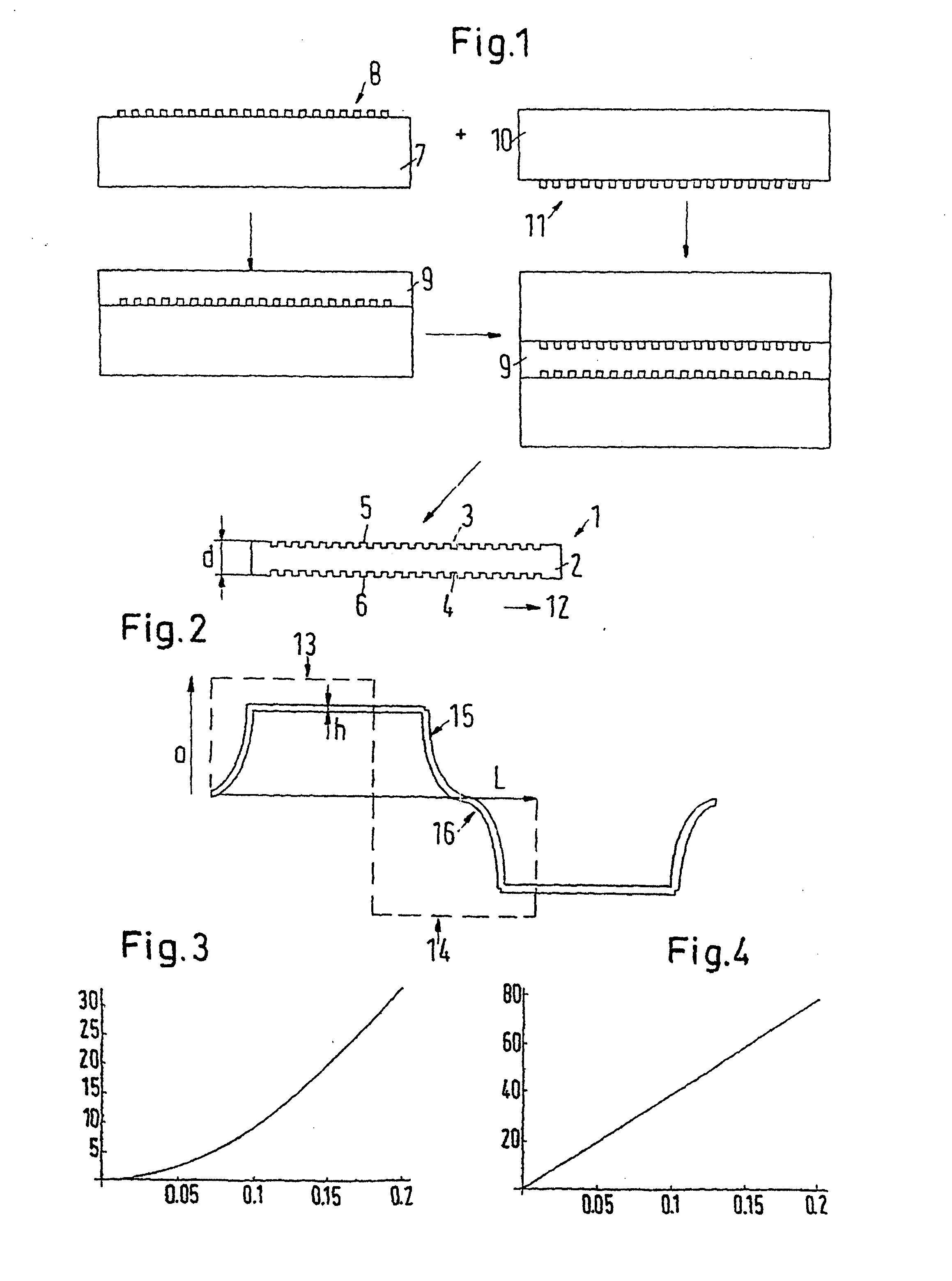
[0008] With this development, one achieves several advantages: since the electrode is formed throughout in the transverse direction, it limits the extension of the body in this transverse direction. “Throughout” here means that the electrode has such a shape that it can not be further stretched, for example, a straight line shape. The entire deformation, which results from a decrease in the thickness of the body, is converted to a change in extension in the longitudinal direction. Naturally in practice because of real materials a change in the transverse direction is also obtained. This is however, in comparison to the change of the extension in the longitudinal direction, negligible. Since the electrode extends continuously over the entire waved region, it is assured that the electric conductivity of the electrode is large enough so that the formation of the electric field, which is required for the reduction of the thickness of the body, occurs rapidly. One can therefore positively realize a high frequency with the actuating member. Since the outer surface of the body is provided with at least one waved region and the waves run parallel to the transverse direction, in the longitudinal direction an outer surface stands available which at least in the rest condition of the actuating member is essentially larger than the longitudinal extent of the actuating member. If one therefore enlarges the longitudinal extent of the actuating member, then only the waves are flattened, that is the difference between the extremes, in other words the crests of the heights and the valleys of the depths, becomes smaller. An electrode, which is applied to this surface, can accordingly follow the stretching without problem without the danger existing that the electrode becomes loosened from the surface. By way of the waved surface one achieves therefore an outstanding stiffness in the transverse direction, a good flexibility in the longitudinal direction, and simple to realize possibility that the electrical voltage supply for creating the electric field can be distributed uniformly over the entire surface of the body. The expression “waved” does not mean that only bow shaped or sinusoidally shaped contours are of concern. Basically, it is taken here that any structure is imaginable and permissible in which “crests” and “valleys” alternate with the crests and valleys extending in the transverse direction, that is in a direction which runs at a right angle to the (extension direction. In cross section, it can therefore concern a sine wave, a triangular wave, a saw tooth wave, a trapezoidal wave or a rectangular wave. The extensibility is improved without influencing the dynamism of the actuating member.
[0009] Preferably, the electrode completely covers the surface of the waved region. A sheet-like electrode is therefore used so that the electrical charge can be transferred to every point of the boundary surface of the body so that the build up of the electric field occurs uniformly. At the same time, it allows the stiffness in the transverse direction to be further improved because not only the extremes, that is the tops of the crests and the bottoms of the valleys, are covered with the through going electrode, but also covered are the flanks between the crests and the valleys. Yet, the movablility in the longitudinal direction essentially changes not at all. When the body extends in the longitudinal direction, the contours flatten, without anything having to change in the arrangement between the electrode and the body.
[0010] It is especially preferred that the electrode be directly connected with the body. An additional conductive layer is more over not necessary, because the electrode takes over the electrical conduction for the entire boundary surface. If the electrode is directly connected with the body, the influence of the electrode on the body is better, which manifests itself especially in an improved stiffness or non-extensibility in the transverse direction.
[0015] Preferably, the rectangular profile has teeth and teeth gaps which in the longitudinal direction are of the same length. This makes it possible that the electric field is formed with most pausible uniformity. At the same time, this shape simplifies the manufacturing.
[0018] It is especially preferred that the conducting layer be applied evaporatively. An evaporatively applied layer allows the desired small thickness to be realized. One can moreover make certain that the evaporated material can also penetrate into narrow valleys and there form an electrode.

Problems solved by technology

Above all, this, because of the poor conductivity of the electric conducting layer, results in a certain limiting of the dynamism of the actuating member.

Method used


Image

  • Actuating member and method for producing the same
  • Actuating member and method for producing the same
  • Actuating member and method for producing the same

Examples


Embodiment Construction

[0024]FIG. 1 shows different steps for the making of an actuating member 1 with a body 2, which body has two boundary surfaces 3, 4 lying oppositely to one another. Applied to each of the boundary surfaces 3, 4 is an electrode 5, 6, respectively. The electrodes 5, 6 are directly connected to the body 2. The body 2 is formed of an elastomer material, for example, a silicone elastomer, and preferably has dielectric properties. The material of the body 2 is of course deformable. It has however, a constant volume, that is if one compresses the body 2 in the direction of the thickness d there then results an increase in the extent of the body 2 in the two other directions. If one then limits the extension of the body 2 in one direction, the decrease in the thickness d leads entirely to an increase of the extension of the body 2 in the other direction. In the case of the exemplary embodiment of FIG. 1 the extension possibility perpendicular to the plane of the drawing (transverse directio...


PUM

PropertyMeasurementUnit
Lengthaaaaaaaaaa
Thicknessaaaaaaaaaa
Pressureaaaaaaaaaa

Abstract

The invention relates to an actuating member comprising an elastomer body that is provided with one electrode each on opposite peripheries. The aim of the invention is to improve the dynamism of such an actuating member. To this end, at least one periphery is provided with at least one waved section that comprises elevations and depressions as the extremes disposed in parallel to the cross direction. Said section is covered by an electrode that completely covers at least a part of the extremes and that extends across the waved section.

Description

CROSS-REFERENCE TO RELATED APPLICATIONS [0001] This application is a Divisional Application of U.S. Ser. No. 10 / 415,631 entitled “Actuating Member and Method for Producing the Same” to Mohamed Y. Benslimane, et al. filed on Aug. 12, 2003 and claims the benefit of the filing date thereof under U.S.C. §120. The present invention also claims priority from and incorporates by reference essential subject matter disclosed in International Application No. PCT / DK01 / 00719 filed on Oct. 31, 2001 and German Patent Application No. 100 54 247.6 filed on Nov. 2, 2000.FIELD OF THE INVENTION [0002] The invention concerns an actuating member with a body of elastomer material which body on each of two boundary surfaces lying oppositely to one another is provided with an (electrode. The invention further concerns a method for making an actuating member with a body of elastomer material which on two oppositely lying sides is provided with electrodes. BACKGROUND OF THE INVENTION [0003] One such actuatin...

Claims


Application Information

Patent Timeline
IPC IPC(8): B05D5/12A61F2/08B81B3/00B81C1/00H01L41/09H02N1/00H02N2/00H02N2/04H04R23/00
CPCB81B3/007B81B2201/038H01L41/0986H01L41/333H02N1/006H04R23/00H01L41/45H10N30/206H10N30/084H10N30/098H02N2/00
Inventor BENSLIMANE, MOHAMED YAHIAGRAVESEN, PETER
Owner DANFOSS AS
Learn More