
Methods and Systems for Monitoring Molecular Interactions

a molecular interaction and molecular technology, applied in the field of methods and systems for monitoring molecular interactions or associations, can solve the problems of not giving rise to a detectable difference, requiring additional time and labor-intensive steps, and complicated measurement of the interaction or reaction process

Inactive Publication Date: 2007-11-15
CALIPER TECH
View PDF23 Cites 94 Cited by
  • Summary
  • Abstract
  • Description
  • Claims
  • Application Information

AI Technical Summary

Benefits of technology

[0020] The invention uses differences in diffusivities of molecules and the mitigating effect of the Taylor-Aris phenomenon on dispersion in molecular assays. A particular advantage of the invention is the ability to determine the interaction between molecules whose ratio of diffusivities is relatively small.
[0021] Also, the invention provides for assay detection methods that do not require labels that generate a discernible signal upon the occurrence of an associative or dissociative molecular interaction, or a separation step following a molecular association of labeled species.
[0022] The invention can be used to determine a variety of interactions between molecules, including associative and dissociative interactions. The methods, devices, and systems disclosed herein are particularly useful in measuring protein binding, such as universal protein binding assays for pharmaceutical libraries.
[0023] Further features and advantages of the present invention are described in detail below with reference to the accompanying drawings.BRIEF DESCRIPTION OF THE FIGURES
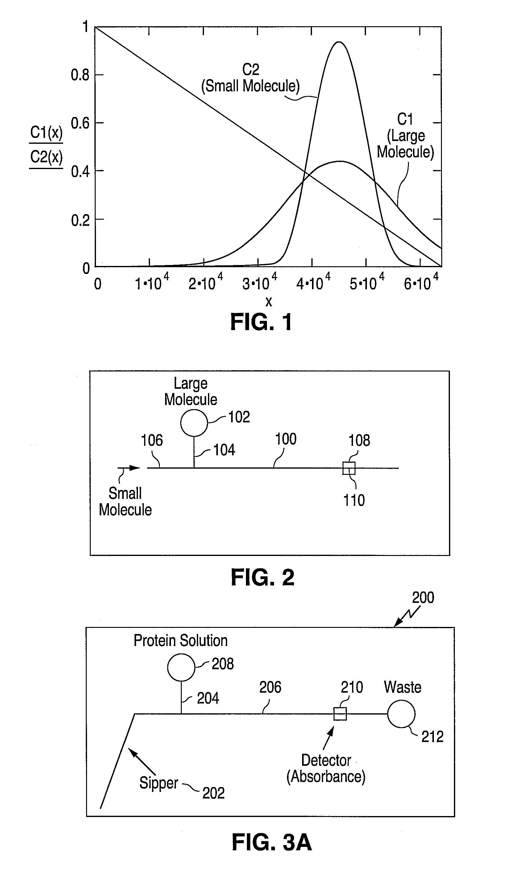
[0024]FIG. 1 shows an expected concentration profile versus channel axial position for a large molecule and a small molecule.
[0025]FIG. 2 shows a schematic representation of a fluid conduit system for practicing the present invention.

Problems solved by technology

The disadvantage of these heterogenous formats is that they require additional time and labor-intensive steps.
However, measurement of the interaction or reaction processes has been complicated by the fact that many analytes of interest (macromolecules including proteins, polynucleotides, polysaccharide and especially small molecules) either (1) do not have a readily available label that produces a signal only when subjected to the reaction of interest, or (2) labeling of the analyte interferes with the molecular interaction.
Furthermore, for many reactions it is apparent that even when one molecule of an interacting pair is labeled, formation of a complex does not give rise to a detectable difference between the complex and the labeled molecule alone.
Therefore, the molecules of many reactions that are of great interest to the biological research field cannot be modified so as to be readily detected by conventional means.
In fluorescence polarization detection, binding of a larger molecule to a small labeled molecule results in a change in the rotational diffusion rate of the labeled species, and thus impedes its ability to emit polarized fluorescence in response to polarized activation energy.
The methods may have several drawbacks, including the lack of optical properties of the subject molecules, the potential for interference by the detection agent or label with the binding or molecular association that is the subject of the experiment, and even the lack of suitable labels for reporting a binding event.
A common problem with methods of the prior art is that a labeled or substrate-bound molecule may not exhibit the identical binding characteristics that its free counterpart would.
By labeling or linking a molecule to a fixed detection substrate, the molecular morphology, binding site availability or accessibility may change, thereby causing inaccurate measurements of its binding characteristics with other molecules.

Method used


Image

  • Methods and Systems for Monitoring Molecular Interactions
  • Methods and Systems for Monitoring Molecular Interactions
  • Methods and Systems for Monitoring Molecular Interactions

Examples


example 1

Protein Binding Assay

Microfluidic Device Design & Instrumentation:

[0098] The microfluidic device design used was a SP299A single sipper chip (Caliper Technologies Corp., Mountain View, Calif.). The microfluidic circuit of the SP299A device is shown in FIG. 6 and consists of a sipping capillary (“sipper”) (not shown) in fluidic connection with a main channel 502 and two side channels 504 and 506. The sipper is physically attached to the chip at point 512.

[0099] The instrument used for this experiment was a Caliper 100 single sipper system (Caliper Technologies Corp., Mountain View, Calif.) (not shown). The instrument included an x-y-z robot that was used to present the microtiter plate to the sipper for sampling reagents stored in the microtiter plates.

[0100] In addition, fluorescent optics (i.e. light source, photodiode, detection / collection lenses, filters etc.) were used to detect samples in the main channel of the device. For this set of experiments, the excitation / emission ...

example 2

Off-Chip Competitive Binding Assay

[0118] This example summarizes how one would implement an off-chip competitive binding assay based on differential Taylor-Aris dispersion of bound and unbound molecules.

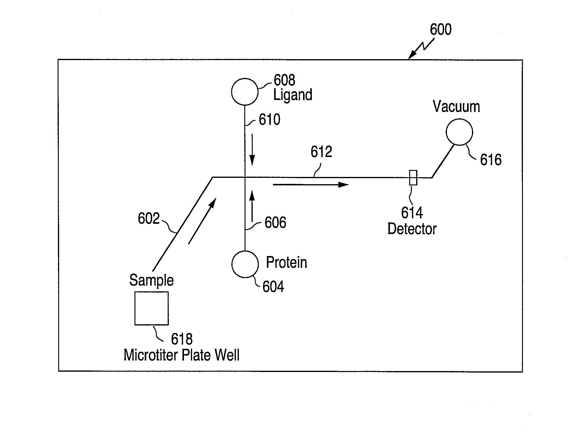
[0119] To perform such an assay, one could use a chip design as illustrated in FIG. 11. Chip 600 includes a sipper 602, two side channels 606 and 610, a main channel 612, reservoirs 604 and 608, detection region 614, and waste 616. External to the chip is a microtiter plate well 618.

[0120] As is illustrated in FIG. 11, both protein and ligand are delivered continuously to main channel 612 from reservoirs 604 and 608 and side channels 606 and 610, respectively, while a small molecule that is being assayed for competitive binding to the protein is drawn up from a microtiter plate well 618 through the sipper 602 in slugs that are separated by buffer spacers. The ligand is known to bind to the protein of interest, and is fluorescently labeled.

[0121] As the ligand is the only fluoresc...


PUM


Abstract

The present invention relates to novel methods and systems for determining the interaction of molecules using the phenomenon of Taylor-Aris dispersion present in fluid flow in conduits. The method involves relating a change in dispersion of molecules to their level of interaction. The present invention also relates to an assay method using Taylor-Aris dispersion in a microfluidic system in order to examine molecular interactions in a variety of chemical and biochemical systems.

Description

CROSS-REFERENCE TO RELATED APPLICATIONS [0001] This application claims the benefit of U.S. patent application Ser. No. 10 / 634,742, filed Aug. 4, 2003, which claims the benefit of U.S. Provisional Patent Application No. 60 / 402,508, filed Aug. 12, 2002, both of which are incorporated herein by reference in their entirety for all purposes.STATEMENT REGARDING FEDERALLY SPONSORED RESEARCH AND DEVELOPMENT [0002] Not applicable. TECHNICAL FIELD OF THE INVENTION [0003] This application discloses novel methods and systems for monitoring molecular interactions or associations using changes in physical properties of the molecules in flowing fluidic systems, such as, e.g., rates of Taylor-Aris dispersion. The invention generally relates to methods of observing changes in levels of association between molecules in fluidic conduits, and preferably, microfluidic channel networks. BACKGROUND OF THE INVENTION [0004] Recent efforts have been directed to the development of microscale assay methods in ...

Claims


Application Information

Patent Timeline
IPC IPC(8): G01N33/00G01N33/558G01N37/00G01N33/566
CPCG01N33/558
Inventor SPAID, MICHAELWOLK, JEFFREY A.
Owner CALIPER TECH
Learn More