
Method and Apparatus for Coating Plastic Optical Fiber with Resin

a technology of plastic optical fiber and resin, which is applied in the direction of cladded optical fiber, instruments, other domestic objects, etc., can solve the problems of large increase in transmission loss and tend to increase in plastic optical fiber transmission loss, so as to reduce plastic optical fiber tension, prevent deformation, and reduce the thickness of plastic optical fiber.

Inactive Publication Date: 2007-11-08
FUJIFILM CORP
View PDF0 Cites 5 Cited by
  • Summary
  • Abstract
  • Description
  • Claims
  • Application Information

AI Technical Summary

Benefits of technology

[0013] The inventors of the present invention examined the condition of the plastic optical fiber during the coating process, and have found that the optical fiber is extended by the heat of the molten resin and thus the optical fiber has irregularity to cause scattering loss at the interface between the core and the clad. The extension of the optical fiber is largely affected by the tension to the optical fiber during the coating process, rather than the temperature of the molten resin. The tension to the plastic optical fiber affected not only by the set tension of the optical fiber feeder but by the shape of the mold (die and nipple) attached to the tip of the extruder of the molten resin. Thus, it is possible to decrease the tension to the fiber by adjusting the shape of the die and the nipple, and thus to control the extension of the optical fiber.
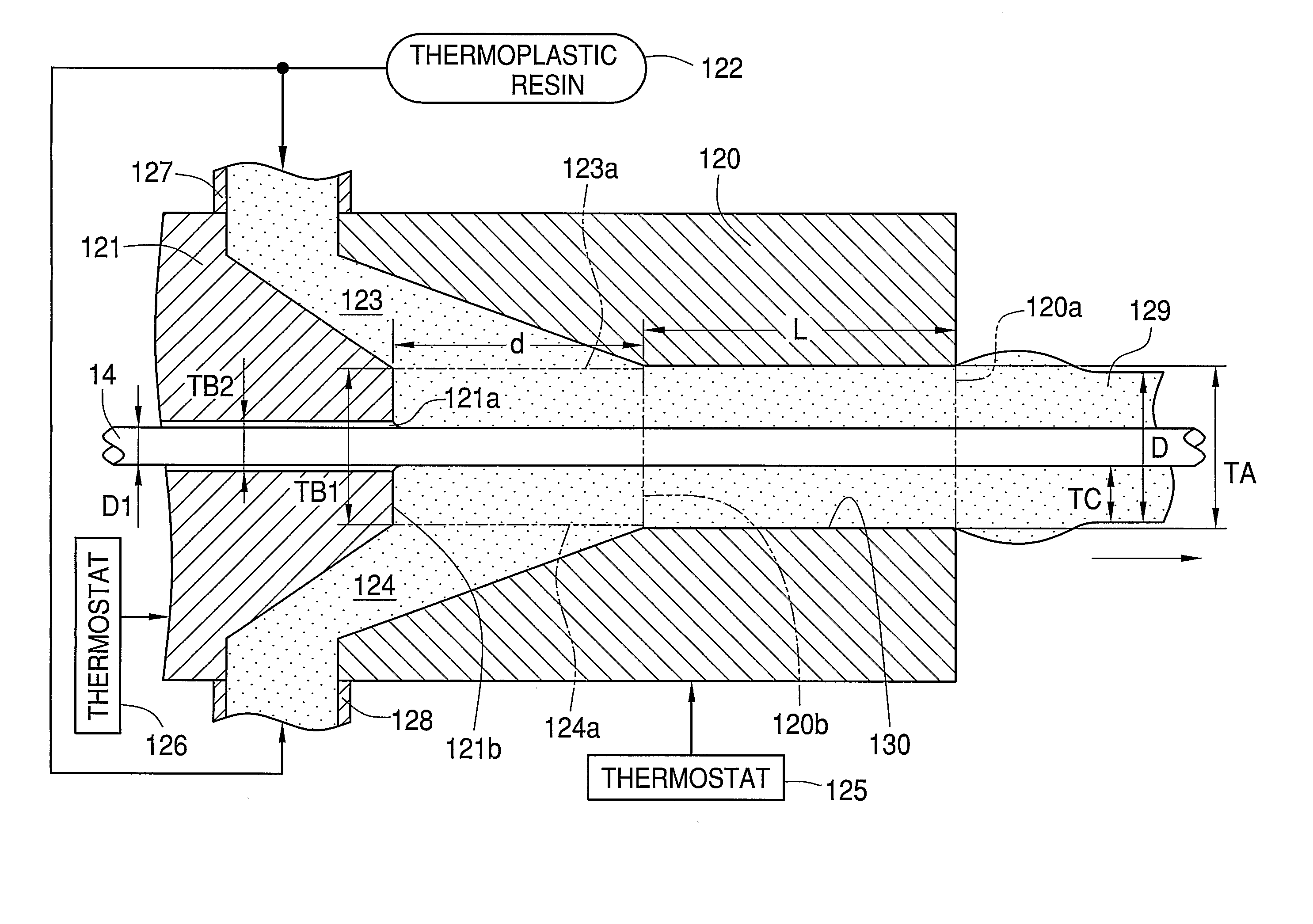
[0020] According to the present invention, since the plastic optical fiber being coated with the thermoplastic resin before reaching the exit of the die, it is possible to reduce the tension to the plastic optical fiber and thus to coat the thermoplastic resin without causing deformation of the plastic optical fiber.
[0021] Moreover, since the die has the cylindrical land portion that is parallel to the outer surface of the plastic optical fiber, the thickness of the plastic optical fiber becomes uniform. Furthermore, satisfying the above described conditions can prevent deformation, stress distribution of the plastic optical fiber, increase in the transmission loss after coating the thermoplastic resin.
[0022] Since the plastic optical fiber is cooled step by step after the thermoplastic resin is coated, it is possible to decrease thermal damage to the plastic optical fiber and to prevent bubbles in the coated layer caused by rapid shrinkage of the thermoplastic resin.

Problems solved by technology

But the material of the core part of the plastic optical fiber, such as PMMA, is sensitive to heat, so the transmission loss of the plastic optical fiber tends to increase due to the heat directly transferred from the molten resin while the molten resin is coated.
Moreover, in the event of manufacturing a graded index type plastic optical fiber having plasticized component, the transmission loss largely increases due to the distribution in the glass transition temperature in the core part is affected by heat.

Method used


Image

  • Method and Apparatus for Coating Plastic Optical Fiber with Resin
  • Method and Apparatus for Coating Plastic Optical Fiber with Resin
  • Method and Apparatus for Coating Plastic Optical Fiber with Resin

Examples


first embodiment

[0063] In the first embodiment, the polymerizable compositions for the clad part are polymerized to form a hollow pipe. Instead, the hollow cylindrical pipe is formed by melt extrusion of a thermoplastic resin (1st process). The core part is formed by interfacial gel polymerization of the polymerizable composition for the core part in the hollow cylindrical pipe, so the preform having the core part and the clad part is produced (2nd process). The preform is subject to change its shape (3rd process) to manufacture the POF. In the 2nd process, the graded index type POF is manufactured by interfacial gel polymerization of the polymerizable compound mixed with the dopant.

[0064] In the second embodiment, the inner clad part is formed inside the hollow pipe (outer clad part) corresponding to the clad part of the first embodiment (1'st process).

[0065] For instance, the hollow cylindrical pipe is formed from a resin including fluorine, such as polyvinylidene fluoride. The cylindrical pipe ...

second embodiment

[0066] Although the double layered cylindrical pipe is formed step by step as described above, it is possible to form the double layered cylindrical pipe by a single step of melt extrusion of the resin including fluorine for the outer clad part and the polymerizable composition for the inner clad part.

[0067] The composition of the polymerizable monomers for the clad part is preferably the same as that for the core part according to the first embodiment. In the second embodiment, the composition of the polymerizable monomers for the inner clad part is preferably the same as that for the core part. The composition ratio of the polymerizable monomers is not necessarily the same, and an accessory ingredient to be added to the polymerizable monomers is not necessarily the same. Providing the same kinds of the polymerizable monomers can improve the optical transmittance and the adhesiveness at the interface between the clad part and the core part (or at the interface between the inner cl...


PUM

PropertyMeasurementUnit
diameteraaaaaaaaaa
melting pointaaaaaaaaaa
melt flow rateaaaaaaaaaa

Abstract

In a coating apparatus, low density polyethylene (122) is flowed in the resin passage (123, 124) between a die (120) and a nipple (121) to form an optical fiber strand having a protective layer (129) on the POF (14). The die (120) and the nipple (121) satisfy the following conditions: D≦TA≦1.3×D TA≦L≦4×TA 0.7×TA≦TB1≦1.3×TA (D1+10) μm≦TB2≦(D1+300 ) μm TA≦d≦2×TA in which TA (μm) indicates the diameter of the die (120), TB1 (μm) indicates the diameter of the nipple (121), TB2 (μm) is the inner diameter of the nipple (121), D1 (μm) is the diameter of the POF (14), D (μm) is the diameter of the optical fiber strand, and d (μm) is the clearance between the die (120) and the nipple (121).

Description

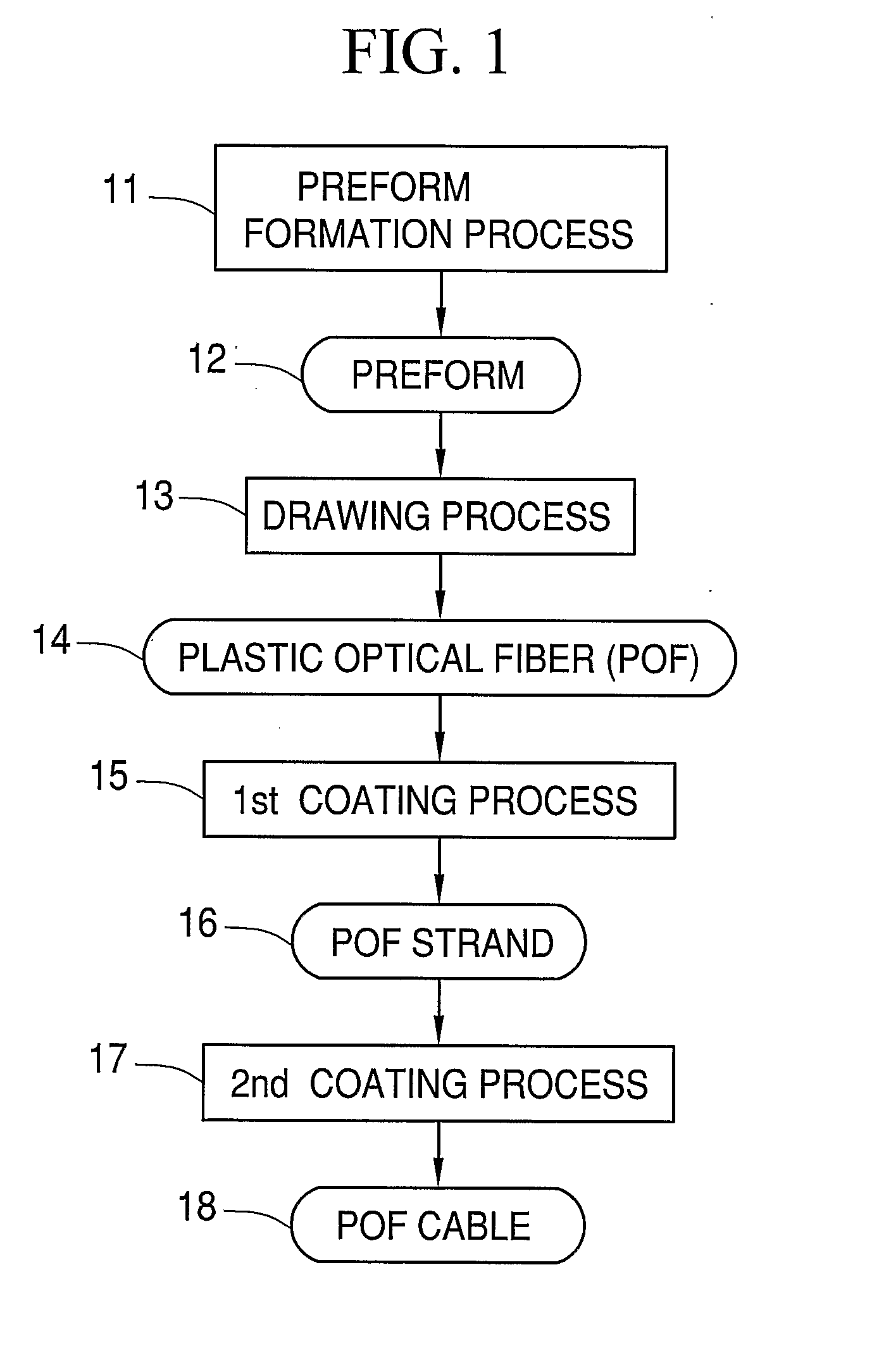
TECHNICAL FIELD [0001] The present invention relates to a method and an apparatus for coating a plastic optical fiber with resin. Background Art [0002] Because of large transmission loss compared with a glass optical fiber, a plastic optical fiber is not suitable in transmitting optical signals for a long distance. Despite larger transmission loss than glass optical fiber, the plastic optical fiber has various merits, such as facility in connection due to a large diameter, facility in fiber terminal process, non-necessity for core alignment with high precision, cost reduction of the connecter, low danger to prick into human body, easy construction, high resistance to vibration and low price. Accordingly, it is planned to utilize the plastic optical fiber not only as household and automobile purposes but as a short-distance, high-capacity cable such as inner wirings for high-speed data processing device and a digital video interface (DVI) link. [0003] The plastic optical fiber (herei...

Claims


Application Information

Patent Timeline
Patent Type & Authority Applications(United States)
IPC IPC(8): B05D5/06
CPCB29D11/00663G02B6/4402G02B6/14G02B6/44
Inventor MIYASAKA, REIKEGASAWA, TADAHIRONAKAMURA, YOSHISADASATO, TAKANORI
Owner FUJIFILM CORP
Learn More