
Liquid crystal display

a liquid crystal display and display technology, applied in non-linear optics, instruments, optics, etc., can solve the problems of texture or light leakage, weak lateral field generation, and reduced aperture ratio

Active Publication Date: 2007-11-08
TCL CHINA STAR OPTOELECTRONICS TECH CO LTD
View PDF6 Cites 15 Cited by
  • Summary
  • Abstract
  • Description
  • Claims
  • Application Information

AI Technical Summary

Benefits of technology

The present invention provides a liquid crystal display with a matrix of pixel electrodes that have a unique design. The pixel electrodes are made up of two parallelogram electrode pieces that have lengthwise and oblique edges. The common electrode faces the pixel electrodes and has tilt direction determining members. The tilt direction determining members may include cutouts and connection portions that meet at a predetermined angle. The pixel electrodes may be connected at their borders. The display also includes thin film transistors, gate lines, data lines, and an organic film. The display may also have color filters with alternating colors. A signal controller controls the drivers and rearranges image signals to apply output image signals to the data driver. The technical effects of this design include improved image quality, reduced power consumption, and improved manufacturing efficiency.

Problems solved by technology

The cutouts or the protrusions decrease the aperture ratio, however.
In this case, however, since the distance between the pixel electrodes is short, a strong lateral field is generated between the pixel electrodes.
Alignment of the liquid crystal molecules is the scattered due to this lateral field and, as a result, texture or light leakage occurs.
Furthermore, liquid crystal displays of a VA mode have poor lateral visibility as compared to a front visibility.

Method used


Image

  • Liquid crystal display
  • Liquid crystal display
  • Liquid crystal display

Examples


Embodiment Construction

[0039] The present invention will be described more fully hereinafter with reference to the accompanying drawings, in which exemplary embodiments of the invention are shown. As those skilled in the art would realize, the described exemplary embodiments may be modified in various different ways, all without departing from the spirit or scope of the present invention.

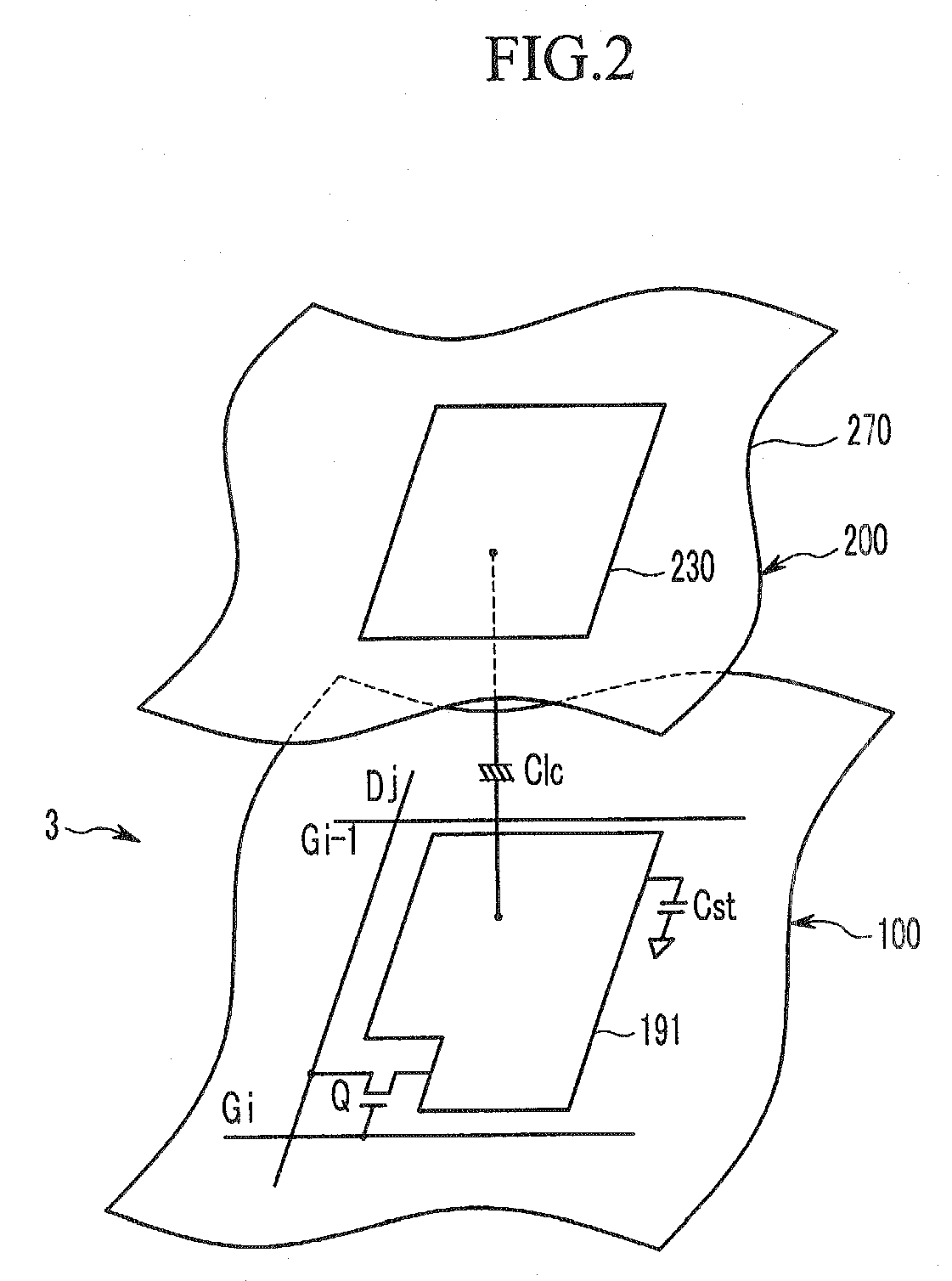
[0040] First, a liquid crystal display according to an exemplary embodiment of the present invention will be described in detail referring to FIGS. 1 and 2.

[0041]FIG. 1 is a block diagram of the liquid crystal display according to an exemplary embodiment of the present invention, and FIG. 2 is an equivalent circuit view of a pixel of the liquid crystal display according to an exemplary embodiment of the present invention.

[0042] As shown in FIG. 1, the liquid crystal display includes a liquid crystal panel assembly 300, a gate driver 400 and a data driver 500 connected to the liquid crystal panel assembly 300, a gray vo...


PUM

PropertyMeasurementUnit
inclination angleaaaaaaaaaa
inclined angleaaaaaaaaaa
angleaaaaaaaaaa

Abstract

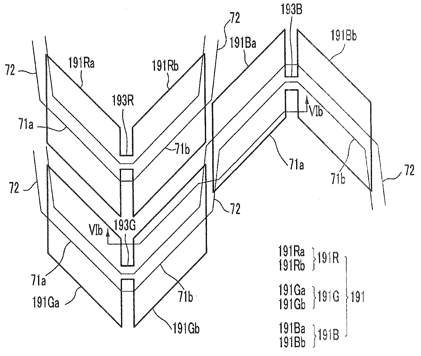
A liquid crystal display includes a plurality of pixel electrodes that are formed in a matrix shape and each of which includes at least two parallelogram electrode pieces each having a pair of lengthwise edges and a pair of oblique edges adjacent the lengthwise edges, and a common electrode that faces the pixel electrodes and that has tilt direction determining members. Transverse center lines of the pixel electrodes that are adjacent each other in a row direction alternate, and the tilt direction determining members that correspond to the pixel electrodes that are adjacent to each other in the row direction are connected to each other in the row direction.

Description

CROSS-REFERENCE TO RELATED APPLICATION [0001] This application claims priority to and the benefit of Korean Patent Application No. 10-2005-0118535 filed in the Korean Intellectual Property Office on Dec. 7, 2005, the entire contents of which are incorporated herein by reference. BACKGROUND OF THE INVENTION [0002] (a) Technical Field [0003] The present disclosure relates to a liquid crystal display. [0004] (b) Discussion of the Related Art [0005] Liquid crystal displays (LCDs) are now widely used as flat panel displays in various kinds of electronic devices. A liquid display typically has two display panels on which field generating electrodes such as pixel electrodes and a common electrode are formed, and a liquid crystal (LC) layer that is interposed between the panels. The LCD generates an electric field in the LC layer by applying voltages to the electrodes, and obtains desired images by controlling the strength of the electric field for determining orientations of LC molecules a...

Claims


Application Information

Patent Timeline
Patent Type & Authority Applications(United States)
IPC IPC(8): G02F1/1337
CPCG02F1/133707G02F2201/122G02F1/1393G02F1/134336G02F1/1337G02F1/1343
Inventor CHOI, NAK-CHOSOHN, JI-WONJUNG, MEE-HYEBYUN, HO-YUNCHO, SEON-AH
Owner TCL CHINA STAR OPTOELECTRONICS TECH CO LTD
Learn More