
Film Actuator Based Mems Device and Method

a technology of micro-electromechanical systems and switching devices, applied in electrostatic/electro-adhesion relays, relays, electrical equipment, etc., can solve the problems of increasing the required actuation voltage needed to operate the device, the device also requires a high actuation voltage, and the application requiring high electrical isolation characteristics is not suitable for use with conventional electrostatic actuation based mems devices. , to achieve the effect of low actuation voltage and increase the electrical isolation

Inactive Publication Date: 2007-11-08
OBERHAMMER JOACHIM +1
View PDF6 Cites 35 Cited by
  • Summary
  • Abstract
  • Description
  • Claims
  • Application Information

AI Technical Summary

Benefits of technology

[0009] It is an object of the present invention to provide a MEMS device that can be used in a wider range of applications by providing increased electrical isolation properties with relatively low actuation voltages.
[0010] Another object of the invention is provide a lower cost MEMS switching device that can be fabricated by processing methods where numerous devices can be produced in a highly paralleled process on a wafer or many wafers simultaneously to substantially reduce manufacturing costs.
[0011] It is another object of the invention to provide a high quality MEMS device that is highly replicable using standard semiconductor fabrication technology.

Problems solved by technology

However, some applications such as those requiring high electrical isolation characteristics are not suitable for use with conventional electrostatic actuation based MEMS devices.
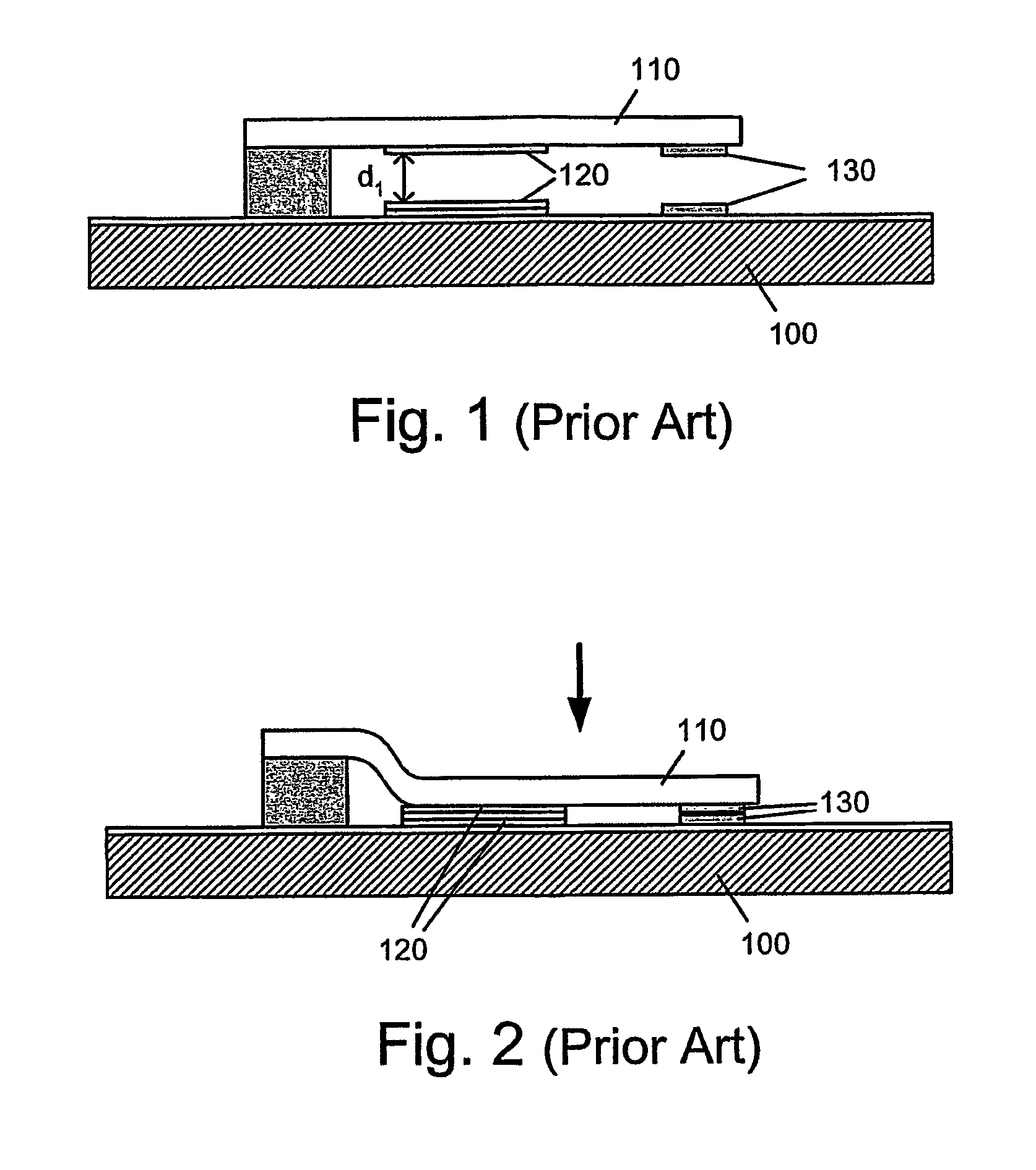
Although providing a large distance between the line contacts 130 leads to a high isolation in the off-state, the disadvantage is that the device also requires a high actuation voltage for overcoming the correspondingly larger distance d1 between the actuation electrodes 120.
The inherent stiffness of the structure undesirably increases the required actuation voltage needed to operate the device.
A conventional way to reduce the actuation voltage is to decrease the gap d1 between the switching contacts 130, however, problems with DC and RF isolation can arise to interfere with operation of the device.
Although relatively low actuation voltages can be achieved with the gas valve, there is no teaching or suggestion on how to adapt the arrangement to work as an electronic switching or RF capacitive tuning device.

Method used


Image

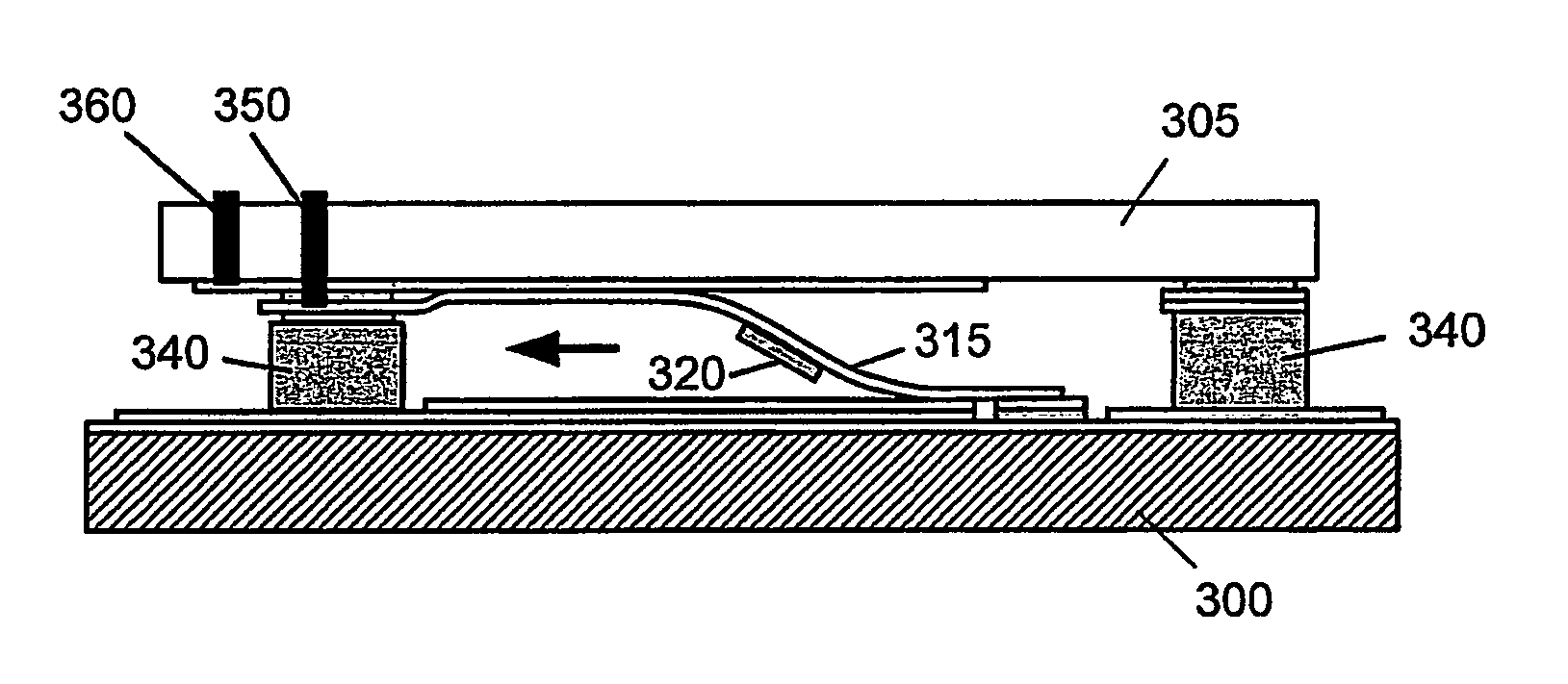
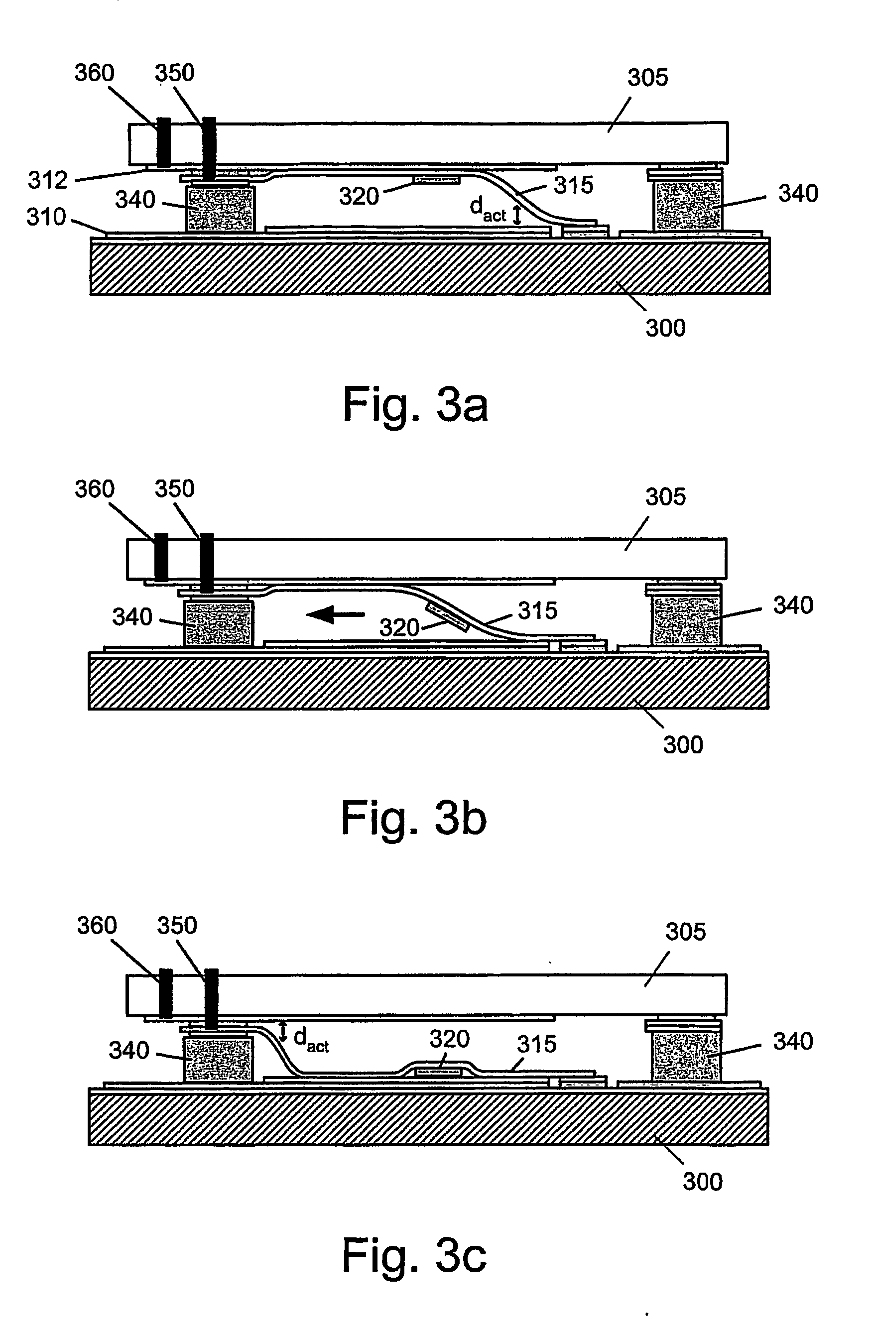
  • Film Actuator Based Mems Device and Method
  • Film Actuator Based Mems Device and Method
  • Film Actuator Based Mems Device and Method

Examples


Embodiment Construction

[0026] The present invention overcomes the disadvantages of the prior art electrostatic MEMS switches by providing the combined features of a large separation distance between the switching contacts while at the same time maintaining a relatively small gap between the actuation electrodes to enable a low actuation voltage for deflecting the membrane e.g. for opening or closing a switch.

[0027]FIGS. 3a-3c illustrates an electrostatic MEMS switching device suitable for switching DC through RF signals operating in accordance with a first embodiment of the invention. The device comprises a thin flexible membrane 315, also referred to as an S-shaped membrane 315 having bottom and top electrodes 310 and 312 respectively and a metal contact block 320 mounted on the membrane 315 that is vertically deflectable between a bottom substrate 300 and a top substrate 305 separated by a small distance. The membrane 315 can be of a non-conducting material with an attached electrode and can itself be ...


PUM

PropertyMeasurementUnit
Pressureaaaaaaaaaa
Flexibilityaaaaaaaaaa
Electrical conductoraaaaaaaaaa

Abstract

The present invention discloses a Micro-Electro-Mechanical systems (MEMS) device suitable for use in a range of applications from DC, such as switching electrical signal lines, to RF applications such as tunable capacitors and switches. In an embodiment of the invention, the device comprises a bottom substrate and a top substrate separated at a fixed distance from each other. Disposed between the substrates is a flexible S-shaped membrane having an electrode or an electrically conducting electrode layer with one end attached to the top substrate and the other end in contact with the bottom substrate. An electrically conducting contact block is attached to the underside of the membrane actuator for short circuiting a signal line when the switch is in the closed position. When a voltage is applied between the membrane and an electrode layer on the bottom substrate, the membrane is induced by electrostatic force to deflect in a rolling wave-like motion such that the contact block is displaced into contact with the signal line. The device can be actively opened when a voltage is applied between the membrane actuator and a electrode layer on the top substrate causing the contact block to displace upward breaking contact with the signal line. The MEMS switching device is applicable for use in a switch matrix board for automatically switching telephone lines or in RF applications in the form of a tunable capacitor.

Description

FIELD OF THE INVENTION [0001] The present invention relates generally to Micro-Electro-Mechanical systems (MEMS) switching devices and, more particularly, to an improved actuation means for said devices that enable for increased isolation characteristics while having lower actuating voltage requirements. BACKGROUND OF THE INVENTION [0002] Interest in Micro-Electro-Mechanical systems (MEMS) devices has increased in recent years due of their potential to reduce costs through the economies gained from batch processing with significant reductions in device sizes. MEMS devices are very small mechanical devices fabricated with standardized integrated circuit technology, offering the advantages of high volume production with excellent uniformity in device properties over the whole wafer and over a whole batch of wafers. MEMS switches are devices that mechanically open (producing an open circuit) or closing to short-circuit a transmission line. Such switches are sub-millimeter in size and o...

Claims


Application Information

Patent Timeline
IPC IPC(8): H01H59/00H01H11/00
CPCH01H59/0009H01H2059/0045Y10T29/49105H01G5/18H01G5/40H01H2059/0072
Inventor OBERHAMMER, JOACHIMSTEMME, GORAN
Owner OBERHAMMER JOACHIM
Learn More