
Selective CO methanation catalysis

Active Publication Date: 2007-11-01
BATTELLE MEMORIAL INST
View PDF34 Cites 17 Cited by
  • Summary
  • Abstract
  • Description
  • Claims
  • Application Information

AI Technical Summary

Benefits of technology

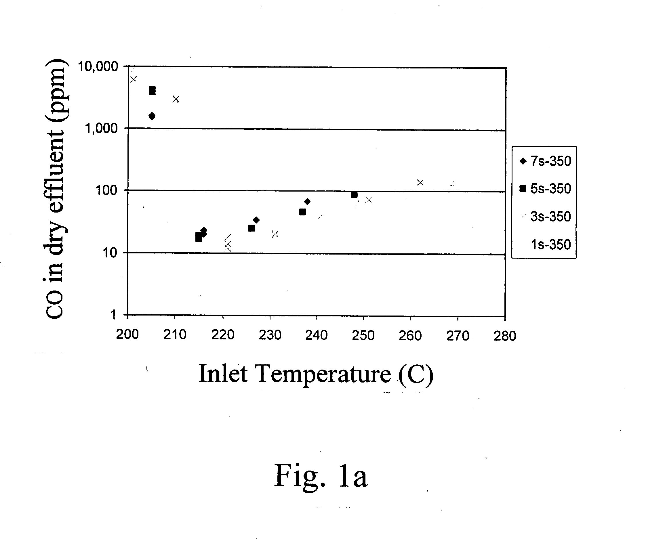
[0006] Baker et al. reported using a ruthenium or rhodium on an alumina support catalyst to selectively hydrogenate carbon monoxide containing high concentrations of carbon dioxide. However, the CO feed concentration used of 0.29% was considerably lower than the percent range needed for current applications as a stand alone process. Additionally, relatively low feed flowrates from GHSV=500-2000 hr−1 were reported. Microreactors at PNNL typically operate at much higher throughputs from 10,000-60,000 hr−1 to maximize reactor efficiency. Even with these lower flowrates the operating temperature ranges where the CO remained below 100 ppm, are undesirably small. Also, only temperatures up to 220° C. were reported. It was found that for a given feed gas, the critical temperature range is shifted somewhat higher as the feed gas average space velocity is increased and also as the feed gas water vapor content is increased.

Problems solved by technology

All three reforming strategies, however, may require additional removal of carbon monoxide since the current permeable membrane fuel cell (PEMFC) cannot operate with carbon monoxide levels higher than several ppm.
Disadvantages include undesirable H2 oxidation and the complexity of having to add precisely controlled amounts of oxygen (air) to the system6.
The main problems with palladium membranes are that they require a high pressure differential, which takes a toll on overall systems efficiency, they usually require temperatures in excess of 350° C., have a high cost associated with the need for a great amount of noble metal, and membrane lifetime is an issue6.
A disadvantage is the hydrogen penalty.
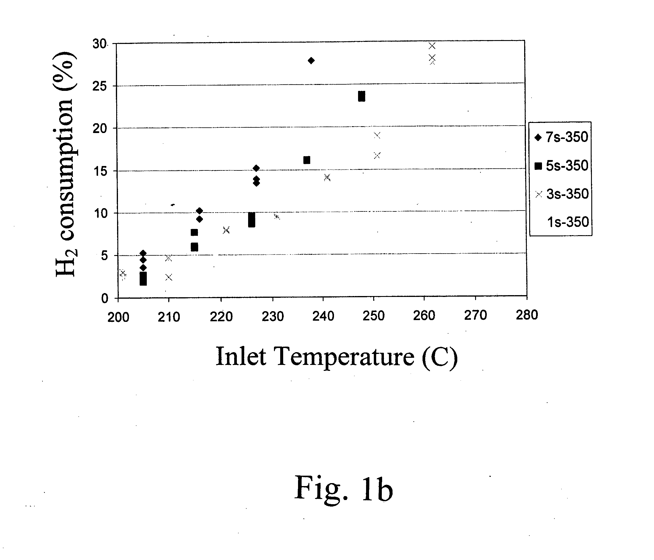
However, the high hydrogen consumption required for both the CO methanation and undesirable CO2 methanation painfully cuts into fuel efficiency.
Thus, many do not believe methanation is feasible at CO concentrations in the percent range6,7.
Even with these lower flowrates the operating temperature ranges where the CO remained below 100 ppm, are undesirably small.

Method used


Image

  • Selective CO methanation catalysis
  • Selective CO methanation catalysis
  • Selective CO methanation catalysis

Examples


examples

[0036] Supported metal catalysts were prepared by impregnation. A neutral γ-Al2O3 support (Engelhard Corp.) was pre-calcined at 500° C. for 2 hrs. A TiO2 P25 extrudate (Degussa) was calcined at 700° C. for 5 hrs. Zr(OH) powder (Aldrich) was calcined at 550° C. for 3hrs to form ZrO2. All supports were kept at 110° C. prior to the incipient-wetness impregnation step. Dilute and concentrated solutions of ruthenium were used requiring multiple and single-step impregnations, respectively. For the multi-impregnations on the alumina support and zirconia, and titania supported catalysts a ruthenium (II) nitrosyl nitrate solution (containing 1.5% Ru, Aldrich) was used. For the single impregnations on alumina support a concentrated ruthenium (III) nitrosyl nitrate solution (containing 9.9% Ru, Colonial Metals) was used. After each impregnation the wet sample was dried in air for at least 8 hour at 110° C. After the final impregnation and drying the sample was calcined at 350° C. for 3 hours. ...


PUM

PropertyMeasurementUnit
Temperatureaaaaaaaaaa

Abstract

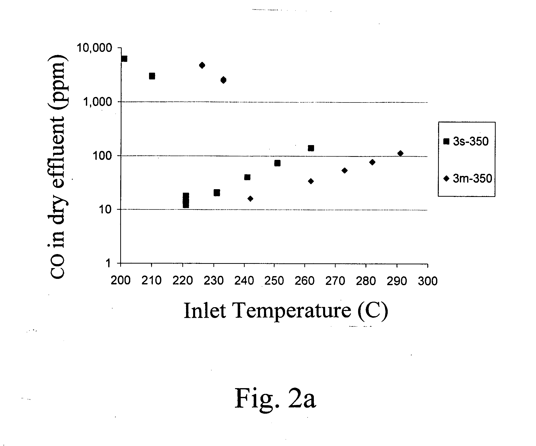
Carbon monoxide (CO) is selectively reacted with hydrogen (H2) over a ruthenium (Ru) on alumina catalyst at a temperature of about 210 to about 290° C. To be a viable option for micro catalytic fuel processing devices, highly active, selective, and stable catalysts must be demonstrated with as large a temperature window for feasible operation as possible. We have studied the effects of metal loading, preparation method, pretreatment conditions, and choice of support on the performance of Ru-based catalysts for such applications. Catalyst testing results and catalyst characterization using XRD and BET are discussed. In one example, operating at a gas hourly space velocity (GHSV) of 13,500 hr−1, a 3% Ru / Al2O3 catalyst yielded CO outputs less than 100 ppm in a temperature range from 240° C. to 285° C., while not exceeding a hydrogen consumption of 10%. This catalyst was further successfully demonstrated in a microchannel device.

Description

STATEMENT OF GOVERNMENT RIGHTS [0001] This work was conducted with funding by the U.S. Army Communications-Electronics Command and the Office of Naval Research under contracts DAAD05-99-D-7014, CP050746, and DABT63-99-C-0039. The government has certain rights in the invention.INTRODUCTION [0002] In recent years, fuel processing including hydrogen generation, purification, and storage is drawing a great deal of attention. Fuel cell systems are being developed for several applications, including distributed and portable power generation and for consumer applications1. At Pacific Northwest National Laboratory (PNNL) much development has been done in the area of fuel processing for portable power generation using microchannel technology2,3,4. Typical fuel processing strategies include steam reforming, partial oxidation and—as a combination of these processes—autothermal reforming5. Both preferential oxidation and autothermal reformation introduce oxygen (air) into the system and burn wi...

Claims


Application Information

Patent Timeline
IPC IPC(8): C01B3/02
CPCB01J21/04B01J23/462B01J35/002B01J35/006C01B2203/047B01J2219/00781C01B3/586C01B2203/0445B01J35/1019B01J35/393B01J35/30B01J35/615
Inventor DAGLE, ROBERTWANG, YONGXIA, GUANGUANG
Owner BATTELLE MEMORIAL INST
Learn More