
Structure and method for reduced corrosion of auxiliary poles during the fabrication of perpendicular write heads

a technology of auxiliary poles and write heads, which is applied in the direction of head surfaces, instruments, and heads with metal sheet cores, etc., can solve the problems of trailing shield corrosion, affecting the operation of the head, and corrosion of the trailing shields. corrosion, and achieve the effect of reducing corrosion

Inactive Publication Date: 2007-10-25
WESTERN DIGITAL TECH INC
View PDF22 Cites 29 Cited by
  • Summary
  • Abstract
  • Description
  • Claims
  • Application Information

AI Technical Summary

Benefits of technology

[0022] It is another object of the present invention to provide a method for making a magnetic head for perpendicular recording having an auxiliary pole with reduced corrosion including depositing a main pole having a top surface, depositing a gap layer on the top surface, and depositing an auxiliary pole on the gap layer, the auxiliary pole having a projected area covering a portion of the gap layer. The method further includes etching a portion of the gap layer, subsequent to depositing the auxiliary pole, such that a remaining portion of the gap layer is greater than the projected area.

Problems solved by technology

During the manufacture of perpendicular write head structures, particularly those that contain trailing shields (also known as auxiliary poles), it has been observed that corrosion of the trailing shields may occur subsequent to the deposition of these structures by electroplating.
This corrosion can occur very quickly, before protective encapsulation can be applied.
Due to the small dimensions of the trailing shields, any pitting or corrosion can significantly impact proper operation.
Even microscopic amounts of corrosion of the iron containing alloys comprising the trailing shield can make obtaining the design target throat height difficult to achieve when forming the air bearing surface.
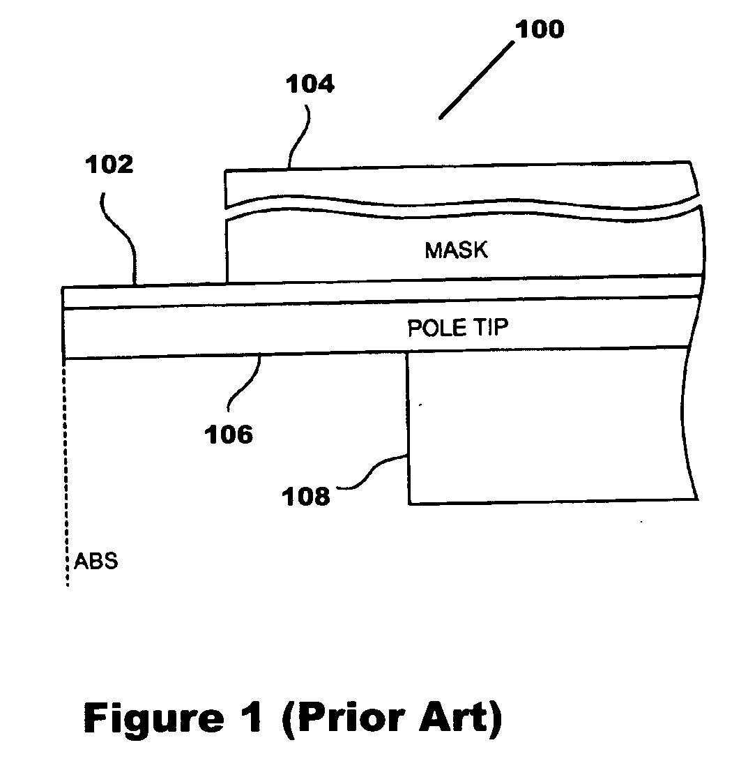
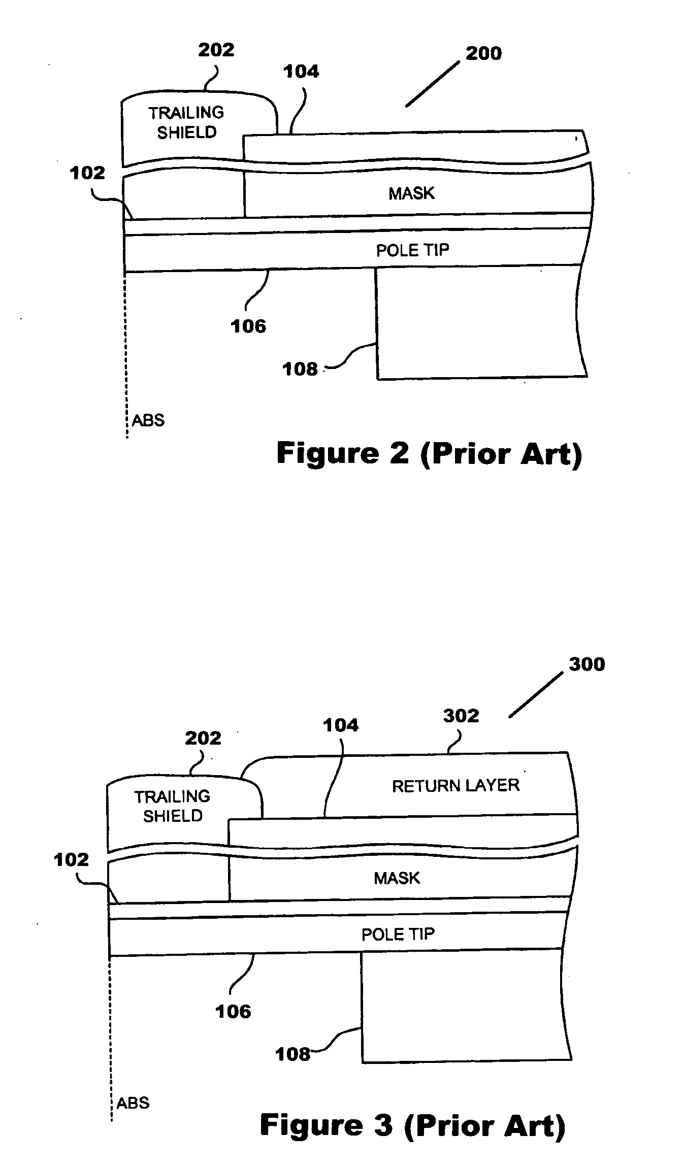
This structure has been found to sensitive to corrosion of the trailing shield, particularly due to the extension of gap 102 layer all the way to the backgap area, particularly for gap materials of Rh and Ru.
This is due to an electrochemical corrosion couple that can corrode the trailing shield 202 quickly after plating.

Method used


Image

  • Structure and method for reduced corrosion of auxiliary poles during the fabrication of perpendicular write heads
  • Structure and method for reduced corrosion of auxiliary poles during the fabrication of perpendicular write heads
  • Structure and method for reduced corrosion of auxiliary poles during the fabrication of perpendicular write heads

Examples


Embodiment Construction

[0035] In subsequent discussion, the term “auxiliary pole” shall be used interchangeably for trailing shields, wrap around shields or similar structures.

[0036] The present invention discloses an improved method and structure for making perpendicular write heads by reducing corrosion of auxiliary poles subsequent to electroplating of these structures, and prior to protective encapsulation. Intermediate photo-resist stripping steps occurring after auxiliary pole deposition can expose these structures to an aqueous environment, causing corrosion of these shield structures, particularly iron containing shields. Corrosion may also occur during subsequent metrology steps which expose the unprotected structures to adsorbed moisture in the environment. For very sensitive structures like auxiliary poles, any corrosion may subsequently impact critical throat dimensions above the write pole, particularly if pitting or oxidation occurs on the surface opposing the ABS (toward the back of the sh...


PUM

PropertyMeasurementUnit
Lengthaaaaaaaaaa
Heightaaaaaaaaaa
Compositionaaaaaaaaaa

Abstract

A method and structure for reducing corrosion during the manufacture of perpendicular write heads is disclosed. Auxiliary pole structures (otherwise known as trailing shields and wrap around shields) are susceptible to corrosion due to their iron containing composition and small dimensions. The impact of corrosion can be reduced by utilizing a gap material comprising an upper surface of noble metals, which extends from underneath the auxiliary pole and is exposed to the same corrosive environment during processing. The area of the exposed gap material is limited to optimize corrosion protection.

Description

BACKGROUND OF THE INVENTION [0001] 1. Field of the Invention [0002] This invention relates to structures and methods for fabricating perpendicular write heads. More specifically, the invention relates to structures and methods for reducing corrosion of trailing shield and wrap around shield (auxiliary pole) structures during the fabrication of perpendicular write heads. [0003] 2. Description of the Related Art [0004] During the manufacture of perpendicular write head structures, particularly those that contain trailing shields (also known as auxiliary poles), it has been observed that corrosion of the trailing shields may occur subsequent to the deposition of these structures by electroplating. This corrosion can occur very quickly, before protective encapsulation can be applied. Due to the small dimensions of the trailing shields, any pitting or corrosion can significantly impact proper operation. For example, the specified throat height (the thickness of the shield at the ABS) of ...

Claims


Application Information

Patent Timeline
IPC IPC(8): G11B5/147
CPCG11B5/1278G11B5/3106Y10T29/49032Y10T29/49052Y10T29/49044Y10T29/49043Y10T29/49046Y10T29/49048
Inventor BONHOTE, CHRISTIANLEE, QUANGLI, JUI-LUNGMACDONALD, SCOTT
Owner WESTERN DIGITAL TECH INC
Learn More