
Mitigation of Harmonic Currents and Conservation of Power in Non-Linear Load Systems

Inactive Publication Date: 2007-10-25
POWER CONSERVATION LTD
View PDF22 Cites 14 Cited by
  • Summary
  • Abstract
  • Description
  • Claims
  • Application Information

AI Technical Summary

Benefits of technology

[0020] An improved power controller system is provided for increasing the operating efficiency and performance of conventional AC induction motors that receive operating power from an electronic controller that employs fast switching circuits to control the application of AC power to the stator windings of the motor. The improved controller system (a) operates efficiently to drive a non-linear mechanical load under light torque loading as well as full-rated torque loading conditions, (b) mitigates harmonic currents from remote sources, (c) mitigates controller-induced harmonic currents, (d) mitigates load-induced harmonic currents, and (e) operates compatibly with KVAR (Kilovolt Ampere Reactive) capacitors that are connected across the stator windings to improve low power factor caused by the high inductive impedance of the induction motor stator windings.
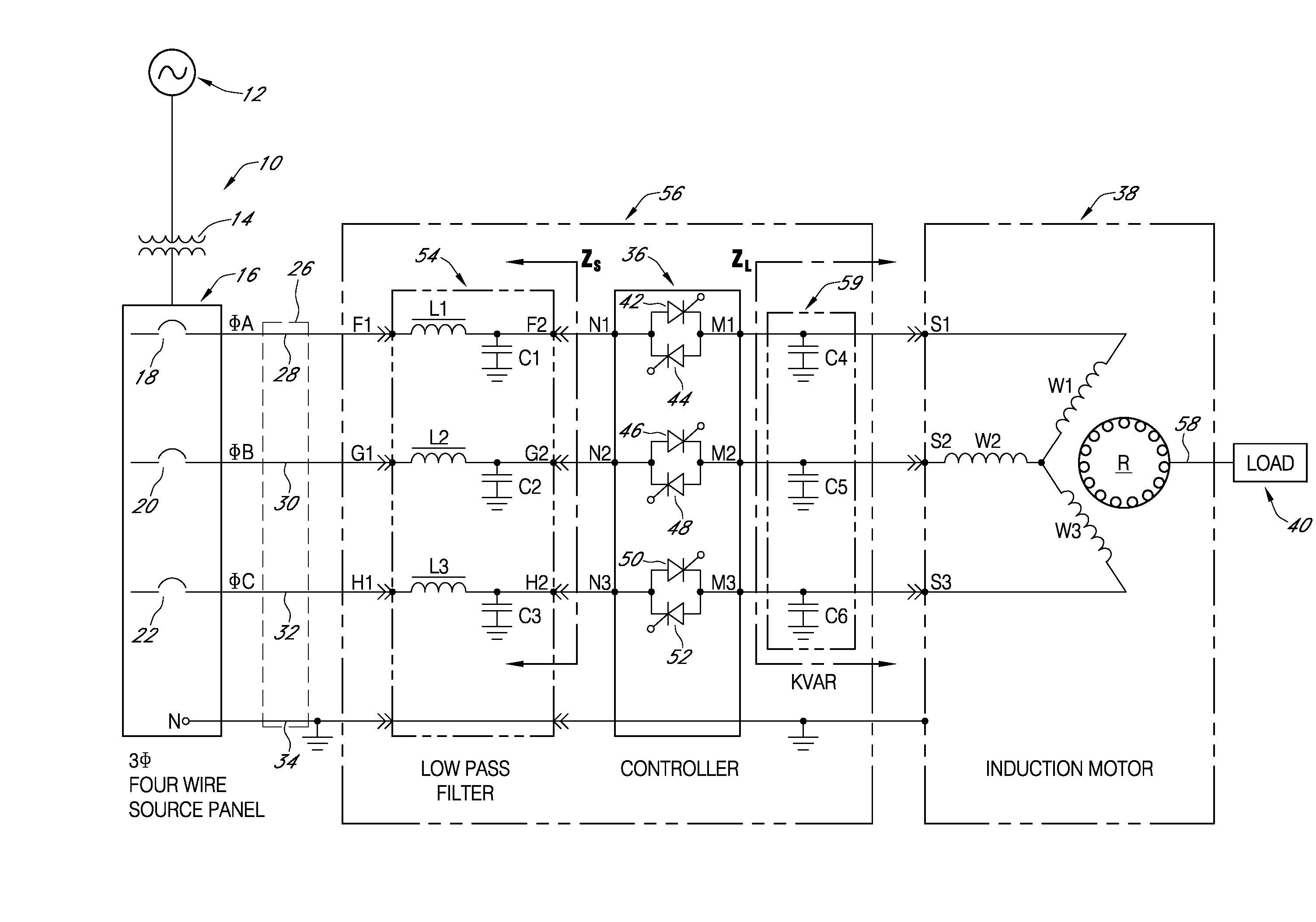
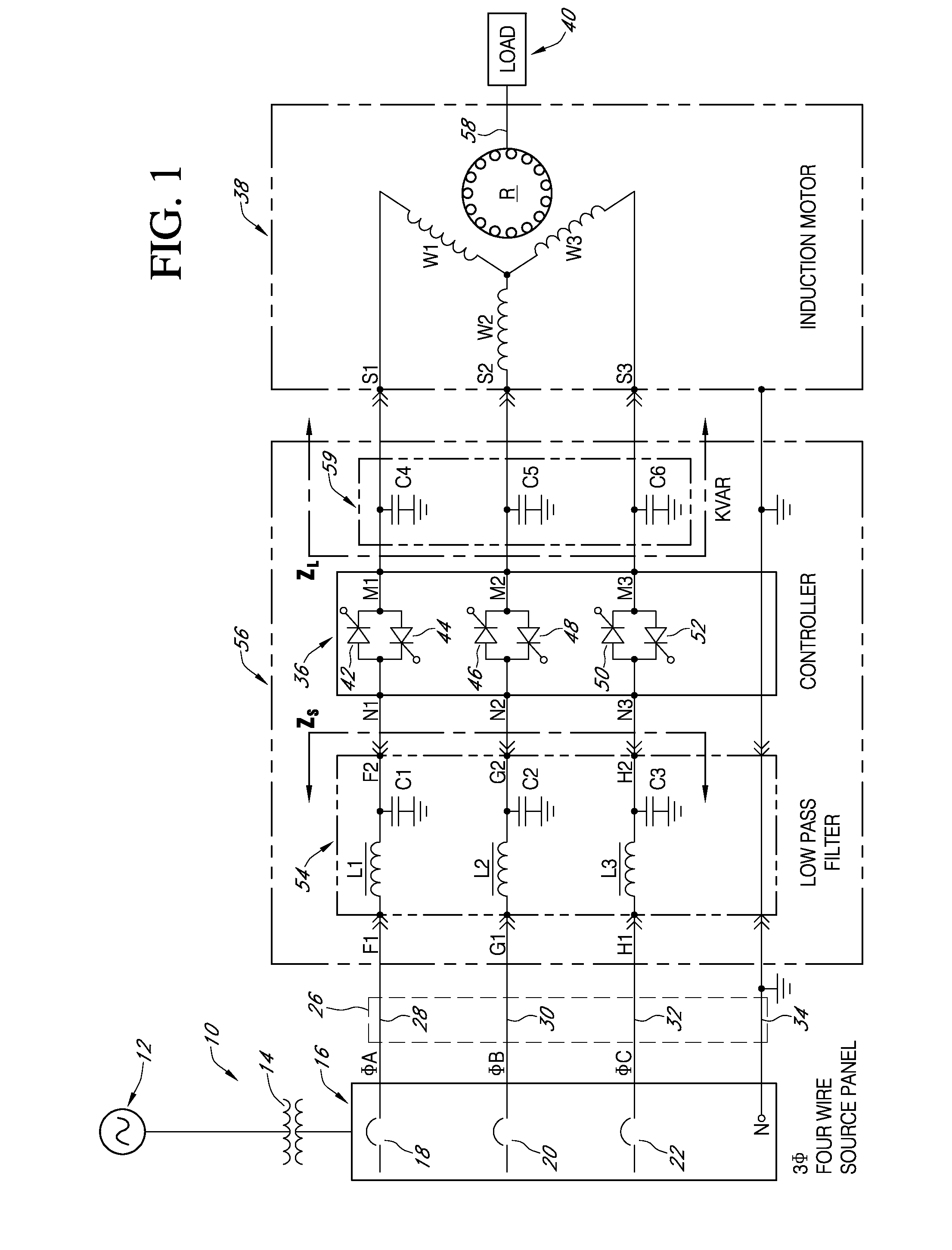
[0021] A primary low pass filter is connected in series between the branch phase conductors and the power controller. KVAR (Kilovolt Ampere Reactive) capacitors are connected across the output terminals of the power controller in shunt to neutral relation. The KVAR capacitor values are coordinated with the inductive reactance values of the stator windings to form a secondary low pass filter across the controller output terminals. The primary and secondary low pass filters isolate the power controller and induction motor with respect to spurious noise and harmonics generated by local as well as remote sources, and also improves real power transfer efficiency from the power generating source to the induction motor.

Problems solved by technology

Spurious noise signals, including harmonic currents, background noise and spike impulse noise are developed on AC power distribution lines.
Such noise signals can originate from the power source, the distribution network, local and remote loads coupled to the network, lightning strikes and distribution equipment malfunction.
The AC supply current delivered from a public utility is not a pure sine wave and contains harmonics that interfere with proper operation of connected equipment.
Additionally, noise and switching transients may be introduced from active loads.
This will introduce harmonics and high frequency noise on the power distribution conductors.
Each load can conduct a significant level of noise and harmonic currents back onto the power line, causing distortion of the power waveform.
Different loads and control devices produce different types and degrees of distortion that may interfere with the operation of the equipment and machines that are being supplied by the distribution network.
The amount of electric power used by machinery and the machinery itself can be affected by waveform distortions present in a power distribution system.
The injection of harmonic currents into the power distribution system can cause overheating of transformers and high neutral currents in three phase, grounded four wire systems.
As harmonic currents flow through the distribution system, voltage drops are produced for each individual harmonic, causing distortion of the applied voltage waveform, which is applied to all loads connected to the distribution bus.
These harmonic fluxes cause heat build-up and additional losses in the motor magnetic core, which reduce power transfer efficiency.
Induction motors can be damaged or degraded by harmonic current heating if the supply voltage is distorted.
The combination of these effects reduce power transfer efficiency and can cause motors to overheat and burn out.
Each harmonic of the fundamental frequency, depending on whether it is a positive, negative, or zero sequence, and its percentage of the fundamental, can have an adverse affect on motor performance and temperature rise, as well as increase the energy costs of electrical service that is charged by the utility service provider.
Most utilities charge a penalty to customers when the customers total load power factor is low.
Harmonic current adds to the RMS value of the fundamental current supplied to the load, but does not provide any useful power.
An unacceptable load current phase angle difference can be expected because of the high inductive impedance presented by the stator windings of an induction motor.
When the induction motor is operating under discontinuous load conditions, or when the load is non-linear, high harmonic currents will result, degrading motor performance and reducing power factor.
Harmonic currents produced in the load circuit or that are conducted along the branch power distribution line from remote non-linear sources may find a resonance with the KVAR capacitors, and the resulting high current may cause the capacitors to fail.
These harmonic currents, when combined with the inductive reactance of the distribution network, can also cause premature motor failure due to excessive current flow, heat build-up and random breaker tripping.
Various problems arise in the operation of conventional controllers, particularly when controlling power applied to non-linear loads.
The constantly changing load between peak minimum and maximum values creates severe control difficulties for power factor control systems which must continuously adjust the power delivery to maintain optimum motor efficiency and economy.
Because of the fast on-off switching action (fast dv / dt) of the thyristors, high peak voltage and high switching frequency, the input current on the supply side of the power controller becomes distorted with high frequency switching transients, which cause an increase of harmonic components in the AC power delivered to the induction motor.
Moreover, spurious noise and harmonic currents from remote sources that are conducted down the branch distribution circuit can interfere with the proper switching operation of the controller itself, resulting in loss of power control.

Method used


Image

  • Mitigation of Harmonic Currents and Conservation of Power in Non-Linear Load Systems
  • Mitigation of Harmonic Currents and Conservation of Power in Non-Linear Load Systems
  • Mitigation of Harmonic Currents and Conservation of Power in Non-Linear Load Systems

Examples


Embodiment Construction

[0028] Preferred embodiments of the invention will now be described with reference to various examples of how the invention can best be made and practiced. Like reference numerals are used throughout the description and several views of the drawing to indicate like or corresponding parts.

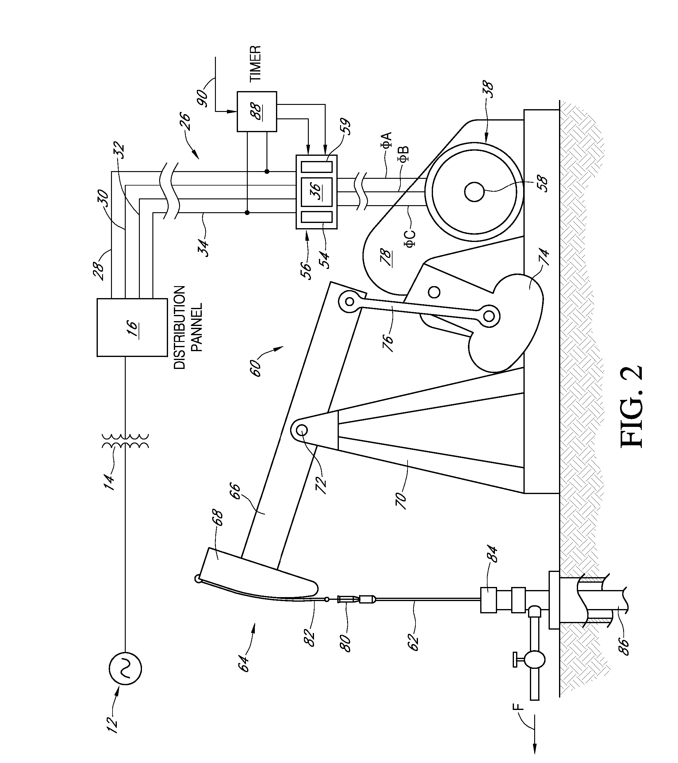
[0029] Referring now to FIG. 1, a conventional AC power distribution network 10 supplies power from a high voltage AC power source 12 to a step-down distribution transformer 14. The distribution transformer feeds power at a reduced voltage level to a distribution panel 16 that includes conventional three phase distribution breakers 18, 20 and 22. AC power at a fundamental frequency of 60 Hz and 480 VAC phase-to-phase (277 VAC phase-to-neutral) is conducted via a four conductor, shared neutral branch circuit 26 containing AC phase conductors 28, 30, 32, and a shared neutral conductor 34.

[0030] Three-phase AC power is applied via the branch circuit conductors to the input terminals N1, N2 and N3 of ...


PUM


Abstract

An AC power controller system applies three-phase AC operating power to an induction motor that drives a non-linear mechanical load. A primary low pass filter is connected in series between branch phase conductors and a power controller of the type that uses gate-controlled switching thyristors for controlling power to the motor. KVAR capacitors connected between the power controller and the induction motor phase windings form a secondary low pass filter across the controller output terminals. The primary and secondary low pass filters isolate the power controller and induction motor with respect to spurious noise and harmonics generated by local as well as remote sources, and also improve real power transfer efficiency from the power generating source to the induction motor by transforming the effective impedance of the power source and induction motor load.

Description

REFERENCE TO RELATED ART [0001] This invention is related to the subject matter of U.S. Pat. No. 6,400,119 entitled “Energy Conserving Motor Controller,” which is assigned to the assignee of the present invention and incorporated herein by reference.BACKGROUND OF THE INVENTION [0002] 1. Field of the Invention [0003] This invention is related generally to AC power distribution systems, and in particular to AC power controller systems that control the application of AC operating power to induction motors. [0004] 2. Description of the Related Art [0005] Spurious noise signals, including harmonic currents, background noise and spike impulse noise are developed on AC power distribution lines. Such noise signals can originate from the power source, the distribution network, local and remote loads coupled to the network, lightning strikes and distribution equipment malfunction. The AC supply current delivered from a public utility is not a pure sine wave and contains harmonics that interfe...

Claims


Application Information

Patent Timeline
IPC IPC(8): H02P27/04
CPCH02P25/16H02P27/16H02P25/22H02P27/00
Inventor GARZA, FILIBERTO D.
Owner POWER CONSERVATION LTD
Learn More