Electromagnetic pump compensation power supply apparatus and electromagnetic pump system
- Summary
- Abstract
- Description
- Claims
- Application Information
AI Technical Summary
Benefits of technology
Problems solved by technology
Method used
Image
Examples
first embodiment
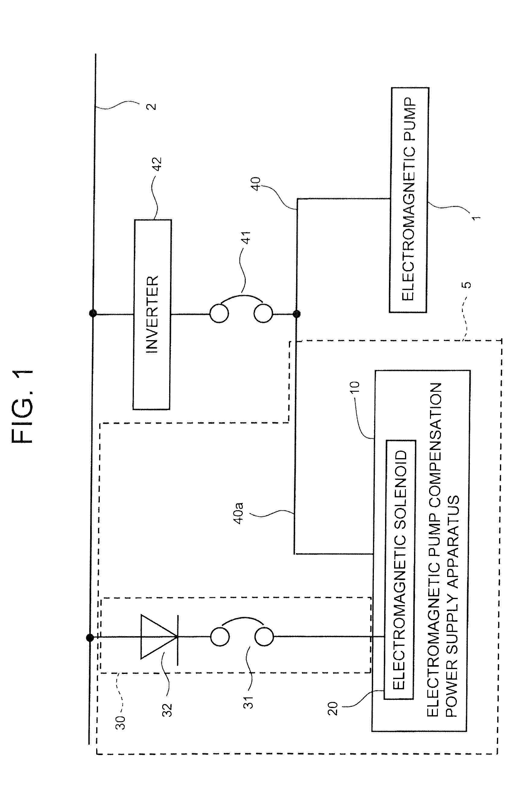
[0028]FIG. 1 is a schematic diagram showing the electrical configuration of a first embodiment of an electromagnetic pump compensation power supply apparatus according to the present invention.
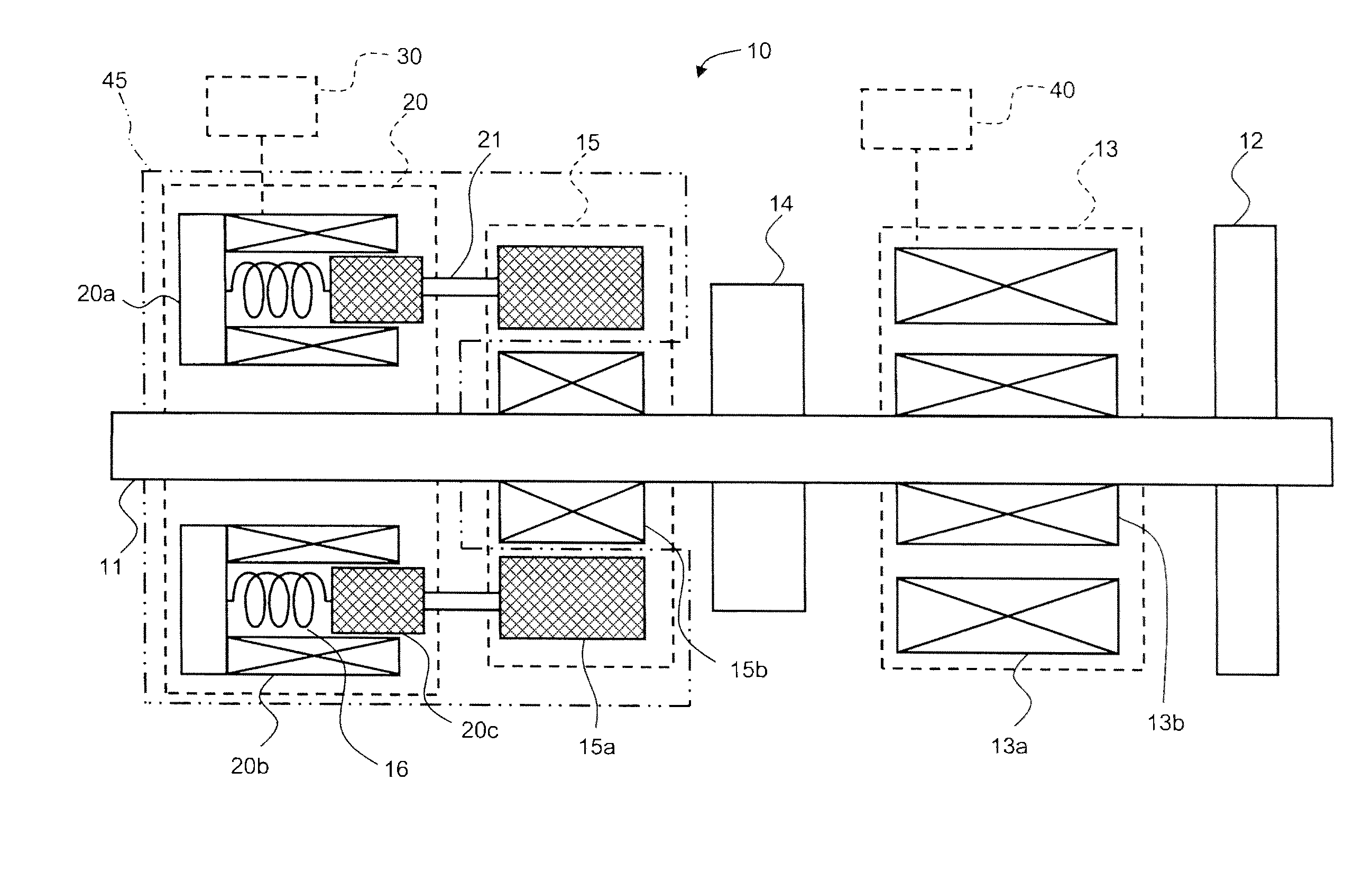
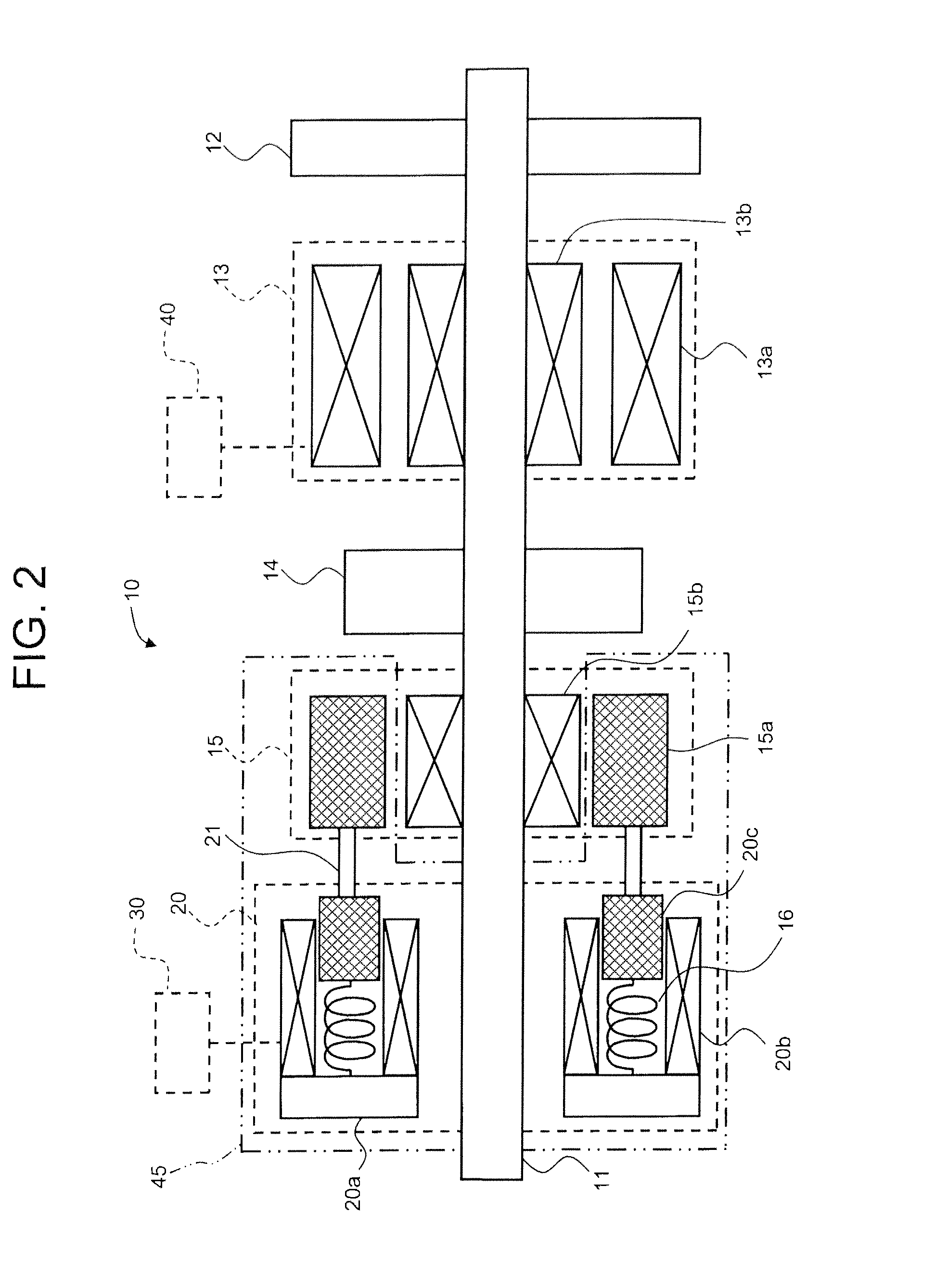
[0029]As shown in FIG. 1, an electromagnetic pump compensation power supply apparatus 5 of the present embodiment includes an electromagnetic pump compensation power supply mechanism 10, a DC power supply unit 30, and a synchronous machine side power supply line 40a.
[0030]To an electromagnetic pump 1, power is fed from an AC system bus 2 via an inverter apparatus 42 and a power supply line breaker 41 which is connected in series to a downstream side of the inverter apparatus 42, and through an AC power line 40.
[0031]To change a flow rate and a pump head characteristics of the electromagnetic pump 1, the inverter apparatus 42 has a function of changing frequency and voltage of drive power for the electromagnetic pump 1 through a process of converting power of the AC system bus 2 from alternate...
second embodiment
[0066]FIG. 3 is a schematic vertical cross-sectional view showing the mechanical configuration of a second embodiment of an electromagnetic pump compensation power supply apparatus according to the present invention.
[0067]As shown in FIG. 3, in an electromagnetic pump compensation power supply mechanism 10 of an electromagnetic pump compensation power supply apparatus 5 of the present embodiment, an exciter stator permanent magnet apparatus 45 has a drive mechanism including exciter stator permanent magnets 15a, a magnetic shield plate 22, electromagnetic solenoids 20, and connecting rods 21.
[0068]A cylindrical magnetic shield plate 22 is provided midway between an exciter stator permanent magnet 15a and an exciter rotor winding 15b in the radial direction; the magnetic shield plate 22 is moved by the electromagnetic solenoids 20 in the axial direction by connecting rods 21.
[0069]The exciter stator permanent magnets 15a and the exciter rotor windings 15b are so positioned as to face...
third embodiment
[0078]FIG. 4 is a schematic diagram showing the electrical configuration of a third embodiment of an electromagnetic pump compensation power supply apparatus according to the present invention.
[0079]According to the present embodiment, as shown in FIG. 4, step-down transformer 33, a DC power supply apparatus 34 and a DC supply line breaker 31 are placed in a DC power supply unit 30 between an AC system bus 2 and electromagnetic solenoids 20, and are connected in series in that order.
[0080]Furthermore, a power factor control unit 35 is provided to control the DC power supply apparatus 34 in such a way as to improve a power factor on the basis of current and voltage signals from a current transformer 36 and a potential transformer 37, which are provided on a power supply line of the electromagnetic pump 1.
[0081]The power factor control unit 35 is designed to continuously control voltage supplied to the electromagnetic solenoids 20 during normal operation.
[0082]The configuration of the...
PUM
 Abstract
Description
Claims
Application Information
 - R&D
- Intellectual Property
- Life Sciences
- Materials
- Tech Scout
- Unparalleled Data Quality
- Higher Quality Content
- 60% Fewer Hallucinations
Browse by: Latest US Patents, China's latest patents, Technical Efficacy Thesaurus, Application Domain, Technology Topic, Popular Technical Reports.
© 2025 PatSnap. All rights reserved.Legal|Privacy policy|Modern Slavery Act Transparency Statement|Sitemap|About US| Contact US: help@patsnap.com


