Catalyst deterioration diagnosis apparatus and catalyst deterioration diagnosis method for internal combustion engine

a technology of deterioration diagnosis and catalyst, which is applied in mechanical equipment, machines/engines, electric control, etc., can solve the problems of deterioration or destruction of catalysts, and affecting the accuracy of diagnosis. , to achieve the effect of accurate diagnosis

Inactive Publication Date: 2007-10-18
MITSUBISHI ELECTRIC CORP
View PDF8 Cites 8 Cited by
  • Summary
  • Abstract
  • Description
  • Claims
  • Application Information

AI Technical Summary

Benefits of technology

[0035]This invention has been made in order to solve such a problem, and it has for its object to provide a catalyst deterioration diagnosis apparatus and a catalyst deterioration diagnosis method for an internal combustion engine, in which even in a case where a deviation has occurred in the output characteristics of O2 sensors on an upstream side and a downstream side, an appropriate amplitude ratio or area equivalent value ratio or an appropriate value obtained by combining the ratios as corresponds to the deteriorated state of a catalyst can be obtained, and robustness is satisfactorily ensured, whereby the deteriorated state of the catalyst can be accurately diagnosed.

Problems solved by technology

The driver of the vehicle, however, is difficult of sensing the deterioration or destruction of the catalyst.
However, when the catalyst has been deteriorated, oxygen concentrations do not become considerably different between on the upstream side and downstream side of the catalyst, on account of the lowering of the O2 storage capability.
Especially, the upstream-side O2 sensor is directly influenced by the heat of the exhaust gas or the sulfur poisoning, and it is therefore liable to undergo the lowering of a response rate and the lowering of an output voltage due to the deterioration.
Accordingly, in the apparatus wherein the deteriorated state of the catalyst is diagnosed by employing the amplitude ratio or area equivalent value ratio of the O2 sensor output signals on the upstream side and downstream side, or a value obtained by combining the ratios, the deteriorated state cannot be detected, or the deterioration is erroneously diagnosed, in the worst case.
Therefore, the amplitude ratio or area equivalent value ratio of the O2 sensor output signals on the upstream side and downstream side, or the value obtained by combining the ratios fluctuates greatly due to the slight deviation of the O2 sensor output characteristics on the upstream side and downstream side, and robustness against the erroneous diagnosis cannot be satisfactorily ensured under such a running condition in some cases.

Method used


Image

  • Catalyst deterioration diagnosis apparatus and catalyst deterioration diagnosis method for internal combustion engine
  • Catalyst deterioration diagnosis apparatus and catalyst deterioration diagnosis method for internal combustion engine
  • Catalyst deterioration diagnosis apparatus and catalyst deterioration diagnosis method for internal combustion engine

Examples


embodiment 1

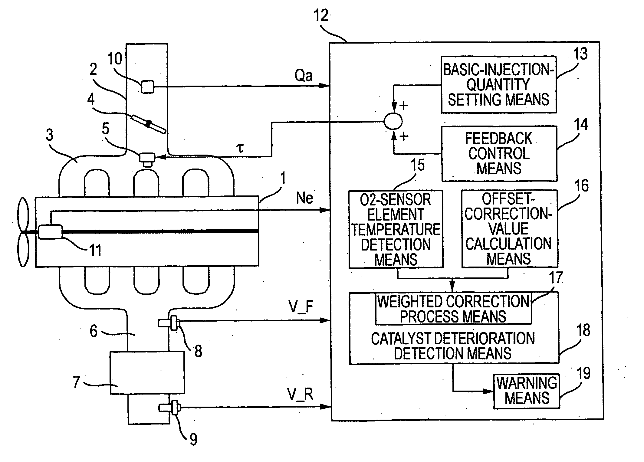
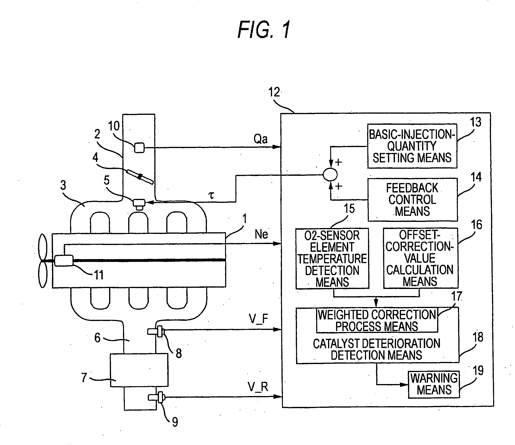
[0058]FIG. 1 is a block diagram conceptually showing the configuration of a catalyst deterioration diagnosis apparatus for an internal combustion engine according to this invention.

[0059]As shown in the figure, in the catalyst deterioration diagnosis apparatus for the internal combustion engine according to this embodiment, a catalyst converter (simply termed “catalyst”) 7 made of a ternary catalyst is interposed in the exhaust pipe 6 of the engine 1.

[0060]Besides, an upstream-side O2 sensor 8 and a downstream-side O2 sensor 9 are respectively disposed in the upstream and downstream of the catalyst 7.

[0061]Both the upstream-side O2 sensor 8 and the downstream-side O2 sensor 9 generate electromotive forces (hereinbelow, termed “output voltages”) which correspond to remaining oxygen concentrations in exhaust gas.

[0062]As shown in FIG. 14, regarding the upstream-side O2 sensor 8 and the downstream-side O2 sensor 9, the output voltages abruptly change especially with a boundary at a the...

embodiment 2

[0107]FIG. 5 is a flow chart showing a weighted correction process routine in a catalyst deterioration diagnosis apparatus for an internal combustion engine according to Embodiment 2 of this invention.

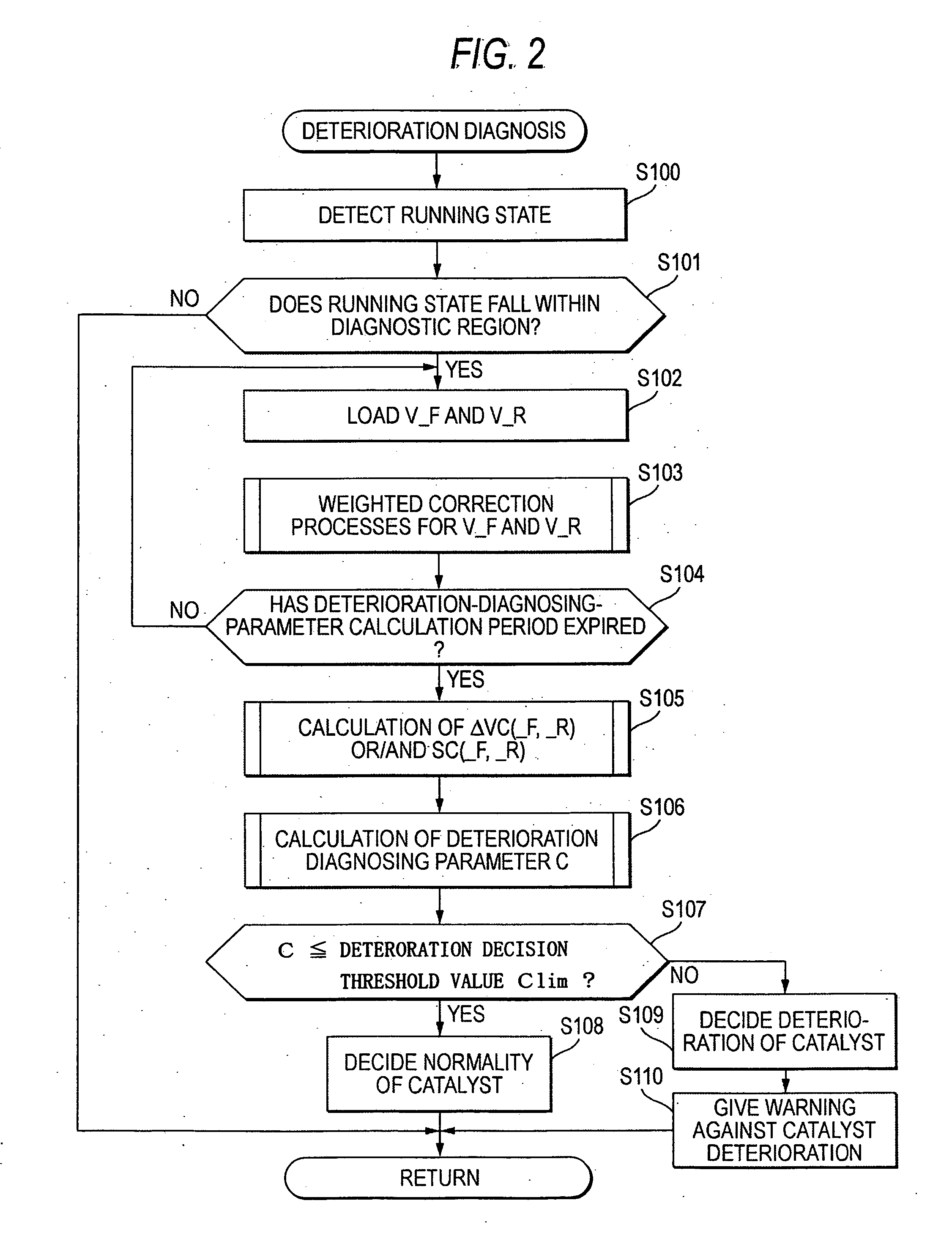
[0108]Embodiment 2 will be described with reference to the flow charts of FIG. 2 and FIG. 5.

[0109]In this embodiment, a weighted correction process is performed by the process routine shown in the flow chart of FIG. 5, in the weighted correction process means 17 shown in FIG. 1.

[0110]In the flow chart of FIG. 5, the processing of steps S300-S302 is added to the flow chart of FIG. 3. First, at the step S300, there are loaded O2 sensor element temperatures on the upstream side and the downstream side as are obtained by the O2 sensor element temperature detection means 15 (refer to FIG. 1).

[0111]Incidentally, although no detailed description is made here, the O2 sensor element temperatures which are detected by the O2-sensor element temperature detection means 15 are actual measurement va...

embodiment 3

[0121]FIG. 7 is a flow chart showing an offset-correction-value calculation process routine in a catalyst deterioration diagnosis apparatus for an internal combustion engine according to Embodiment 3.

[0122]Besides, FIG. 8 is a flow chart showing a deterioration diagnosis operation in the catalyst deterioration diagnosis apparatus for the internal combustion engine according to Embodiment 3.

[0123]Besides, FIG. 9 is a flow chart showing a weighted correction process routine in the catalyst deterioration diagnosis apparatus for the internal combustion engine according to Embodiment 3.

[0124]Now, this embodiment will be described with reference to the flow charts of FIGS. 7, 8 and 9.

[0125]In this embodiment, a process for calculating an offset correction value is first executed by the process routine of the flow chart of FIG. 7 showing the operation of the offset-correction-value calculation means 16 (refer to FIG. 1).

[0126]At a step S400, it is decided whether or not the running state o...


PUM


Abstract

A catalyst deterioration diagnosis apparatus for an internal combustion engine, comprising means for subjecting output signals of an upstream-side and a downstream-side O2 sensors to weighted correction processes corresponding to output levels, means for calculating amplitude magnitudes of the output signals of the upstream-side and the downstream-side O2 sensors after the weighted correction processes, and time integral values of differences between predetermined signals and the output signals of the upstream-side and downstream-side O2 sensors after the weighted correction processes, means for calculating a deterioration diagnosing parameter on the basis of the amplitude magnitudes and the time integral values, means for deciding deterioration of a catalyst converter on the basis of a result of a comparison between the calculated deterioration diagnosing parameter and a predetermined deterioration decision threshold value, and warning means for issuing warning when the catalyst deterioration has been decided.

Description

BACKGROUND OF THE INVENTION[0001]1. Field of the Invention[0002]This invention relates to a catalyst deterioration diagnosis apparatus and a catalyst deterioration diagnosis method which diagnose the deteriorated state of a catalyst converter disposed for the exhaust gas purification of an internal combustion engine, and which gives warning to a driver.[0003]2. Description of the Related Art[0004]An apparatus for purifying the exhaust gas of an internal combustion engine as is extensively put into practical use is one wherein a ternary catalyst converter (hereinbelow, termed “catalyst converter” or simply “catalyst”) which simultaneously oxidizes CO and HC and deoxidizes NOx is disposed in the exhaust system of the engine, while O2 sensors are respectively disposed on the upstream side and downstream side of the catalyst, and an air / fuel ratio feedback control is performed in accordance with the detection signals of the O2 sensors, whereby an air / fuel ratio can be controlled within ...

Claims


Application Information

Patent Timeline
Patent Type & Authority Applications(United States)
IPC IPC(8): F01N3/00F01N7/00F01N3/20F02D41/14F02D41/22F02D45/00
CPCF01N11/007F01N2550/02F01N2560/025F01N2560/06Y02T10/47F02D41/0295F02D41/1441F02D41/1454F01N2560/14Y02T10/40
Inventor MIYASAKO, MASAKAZUWADA, KOJINAKANO, MAKOTO
Owner MITSUBISHI ELECTRIC CORP
Why Eureka
Try Eureka