
Measurement method and arrangement for amplitude and phase synchronization in a polar transmitter

a polar transmitter and phase synchronization technology, applied in the field of wireless communication, can solve the problem of not being able to create an ideal sinusoidal signal, and achieve the effect of reducing the cost and reducing the tuning cost of the polar transmitter

Inactive Publication Date: 2007-10-11
WSOU INVESTMENTS LLC
View PDF7 Cites 11 Cited by
  • Summary
  • Abstract
  • Description
  • Claims
  • Application Information

AI Technical Summary

Benefits of technology

[0014] It is an objective of the present invention to provide a measurement arrangement for measuring an indicator of delay mismatch so that the above-mentioned limitations and drawbacks associated with prior art are eliminated or reduced. It is also an object of the present invention to provide a mobile communication device in which the above-mentioned limitations and drawbacks associated with the prior art are eliminated or reduced. It is also an object of the present invention to provide a set of integrated circuits (chip-set) that can be used in a polar transmitter so that the limitations and drawbacks associated with prior art are eliminated or reduced. It is also an object of the present invention to provide a measurement method for measuring an indicator of delay mismatch so that the limitations and drawbacks associated with prior art are eliminated or reduced.
[0020] search time needed for finding optimal or sufficiently good settings for adjustable delay elements of a polar modulator is reduced,
[0022] cost savings are achieved since time needed for testing and tuning polar transmitters is reduced due to the above-mentioned reasons.

Problems solved by technology

In practice it is not possible to create an ideal sinusoidal signal.

Method used


Image

  • Measurement method and arrangement for amplitude and phase synchronization in a polar transmitter
  • Measurement method and arrangement for amplitude and phase synchronization in a polar transmitter
  • Measurement method and arrangement for amplitude and phase synchronization in a polar transmitter

Examples


Embodiment Construction

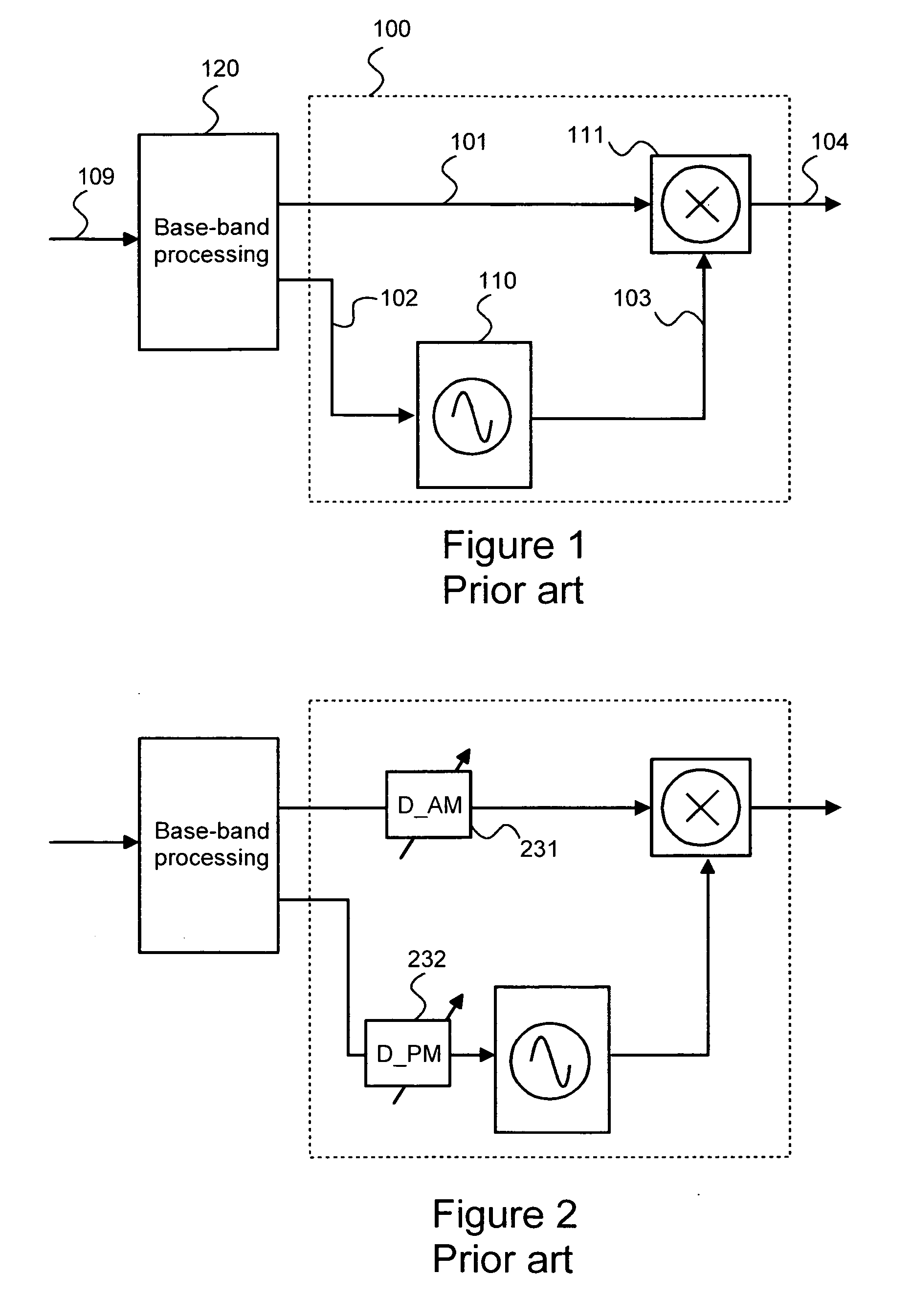
[0054]FIGS. 1 and 2 have been explained above in the description of the prior art.

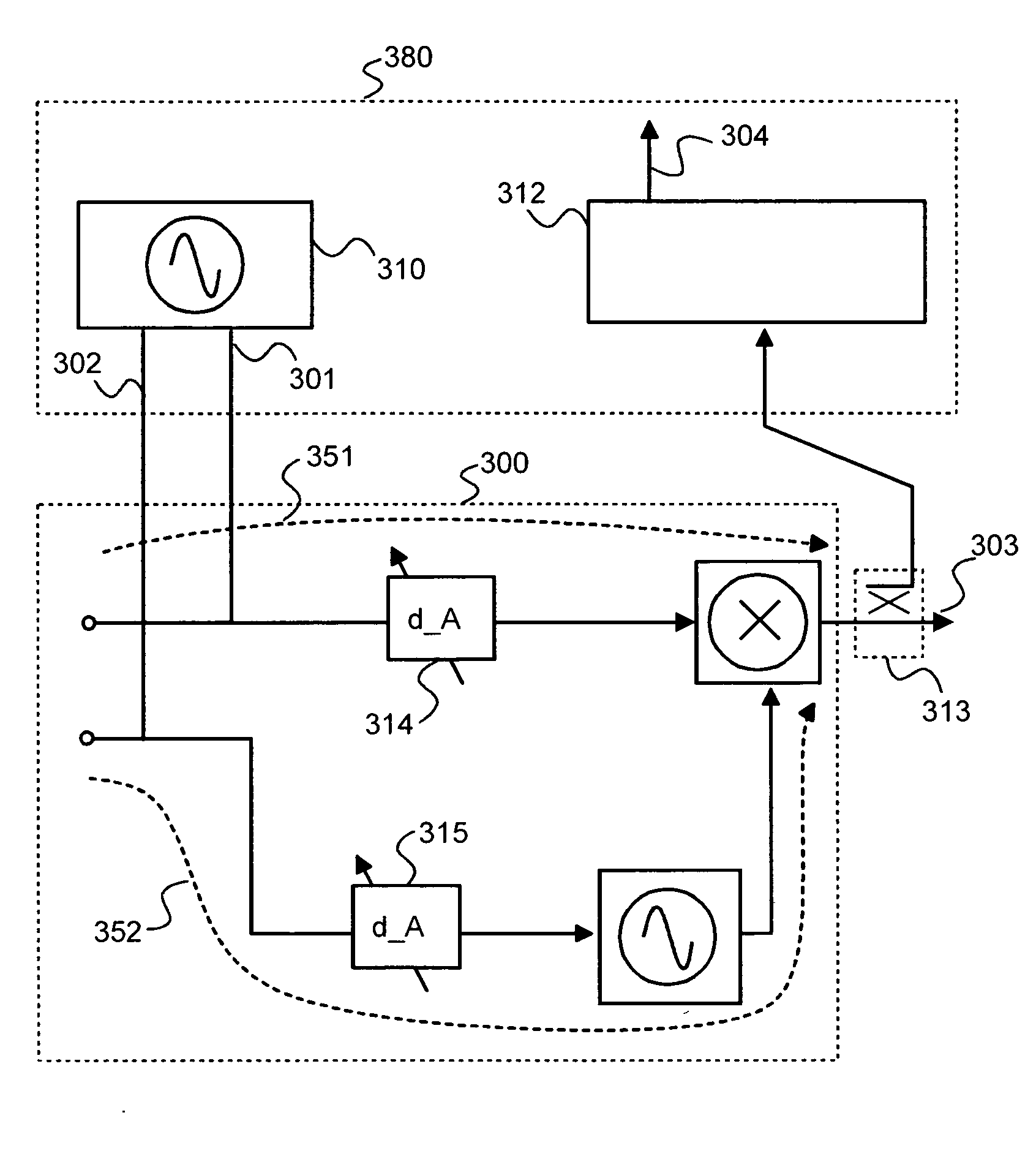
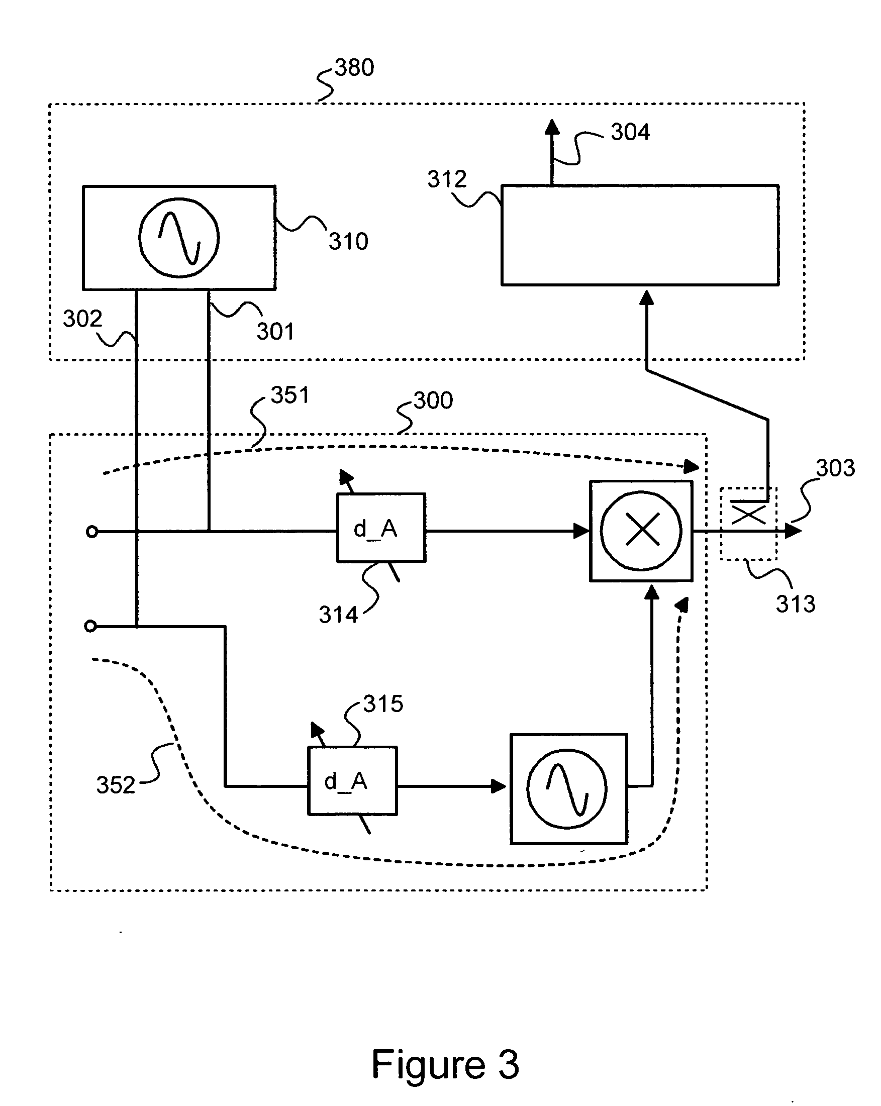
[0055]FIG. 3 shows a high level block diagram of a measurement arrangement according to an embodiment of the invention and a polar modulator 300 coupled to the measurement arrangement. The measurement arrangement 380 comprises a signal generator 310 disposed to feed a first measurement signal 301 having a substantially sinusoidal alternating component into an amplitude information path 351 (A-path) of the polar modulator 300 and to feed a second measurement signal 302 having a substantially sinusoidal alternating component into a phase information path 352 (P-path) of the polar modulator, the alternating component of said first measurement signal and the alternating component of said second measurement signal having same frequency. The measurement arrangement 380 comprises a measurement circuitry 312 disposed to measure an indicator of delay mismatch 304. Said indicator 304 is a quantity that is propo...


PUM


Abstract

A method and arrangement is shown for measuring an indicator of delay mismatch between a phase information path and an amplitude information path of a polar modulator. In the solution according to the invention a substantially sinusoidal measurement signal (301, 302) is injected both into the amplitude information path (351) and into the phase information path (352). An indicator of the delay mismatch is obtained by measuring a quantity that is proportional to a difference between power represented by a lower side band of a spectrum of a polar modulated signal and power represented by an upper side band of the spectrum.

Description

FIELD OF THE INVENTION [0001] The present invention generally relates to wireless communication and particularly relates to a measurement method and an arrangement for amplitude and phase synchronization in a polar transmitter. BACKGROUND OF THE INVENTION [0002] Wireless communication standards, such as GSM (Global System for Mobile Communication), EDGE (Enhanced Data Rates through GSM Evolution), and WCDMA (Wideband Code Division Multiple Access), require a variety of digital modulation formats like 4-PSK, 8-PSK (Phase Shift Keying), and various QAM implementations (Quadrature Amplitude Modulation). A general trend of evolution in the field of wireless communication is an aim for increased data rates (bits / second) and increased spectral efficiency (bits / Hertz). [0003] Using a traditional linear modulation method, such as a traditional Cartesian QAM, imposes stringent linearity requirements for a power amplifier of a transmitter. Biasing the power amplifier to linear operating point...

Claims


Application Information

Patent Timeline
Patent Type & Authority Applications(United States)
IPC IPC(8): H04L25/03
CPCH03C5/00H04L27/366H04L27/361
Inventor SHAKESHAFT, NIALL ERIC
Owner WSOU INVESTMENTS LLC
Learn More