Packet Communication System
a communication system and packet technology, applied in the field of packet communication system, can solve the problems of increasing the overhead of ip packets and difficulty for each telephone to pre-store ip addresses, and achieve the effect of reducing the overhead of ip packets and increasing the transmission delay of voice packets
- Summary
- Abstract
- Description
- Claims
- Application Information
AI Technical Summary
Benefits of technology
Problems solved by technology
Method used
Image
Examples
embodiment 1
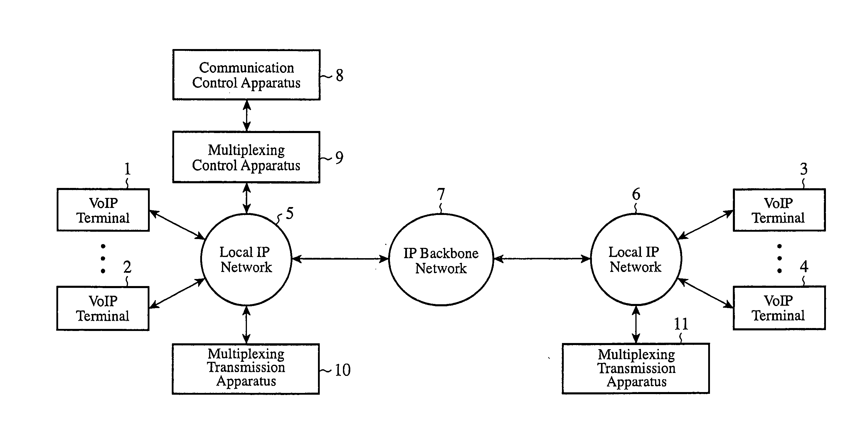
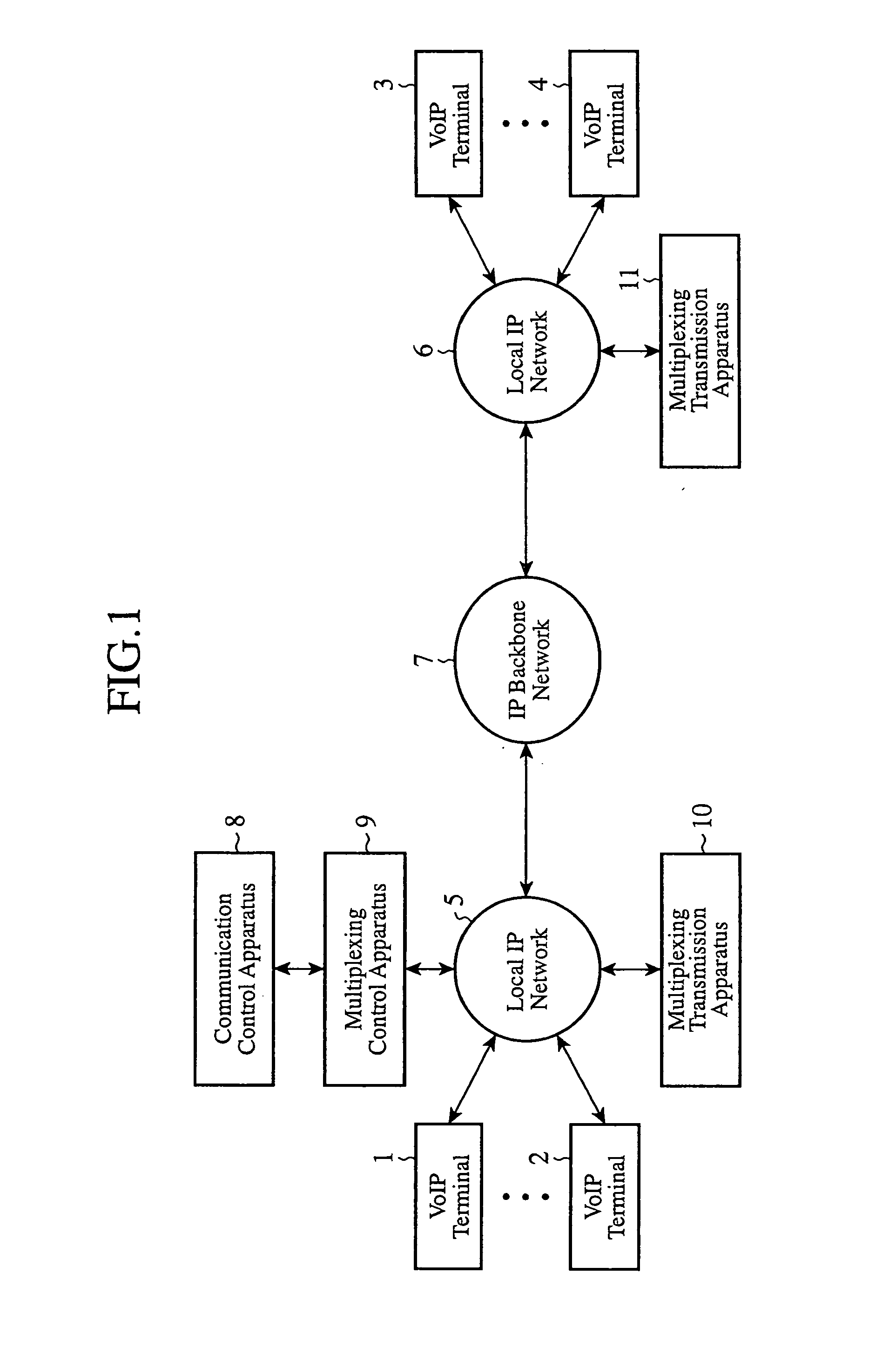
[0035]FIG. 1 is a block diagram showing a packet communication system in accordance with embodiment 1 of the present invention. In the figure, each of VoIP terminals 1 to 4 is a terminal device, such as a telephone or a facsimile, the VoIP terminals 1 and 2 are connected to a local IP network 5, and the VoIP terminals 3 and 4 are connected to a local IP network 6. The local IP networks 5 and 6 are connected to an IP backbone network 7.
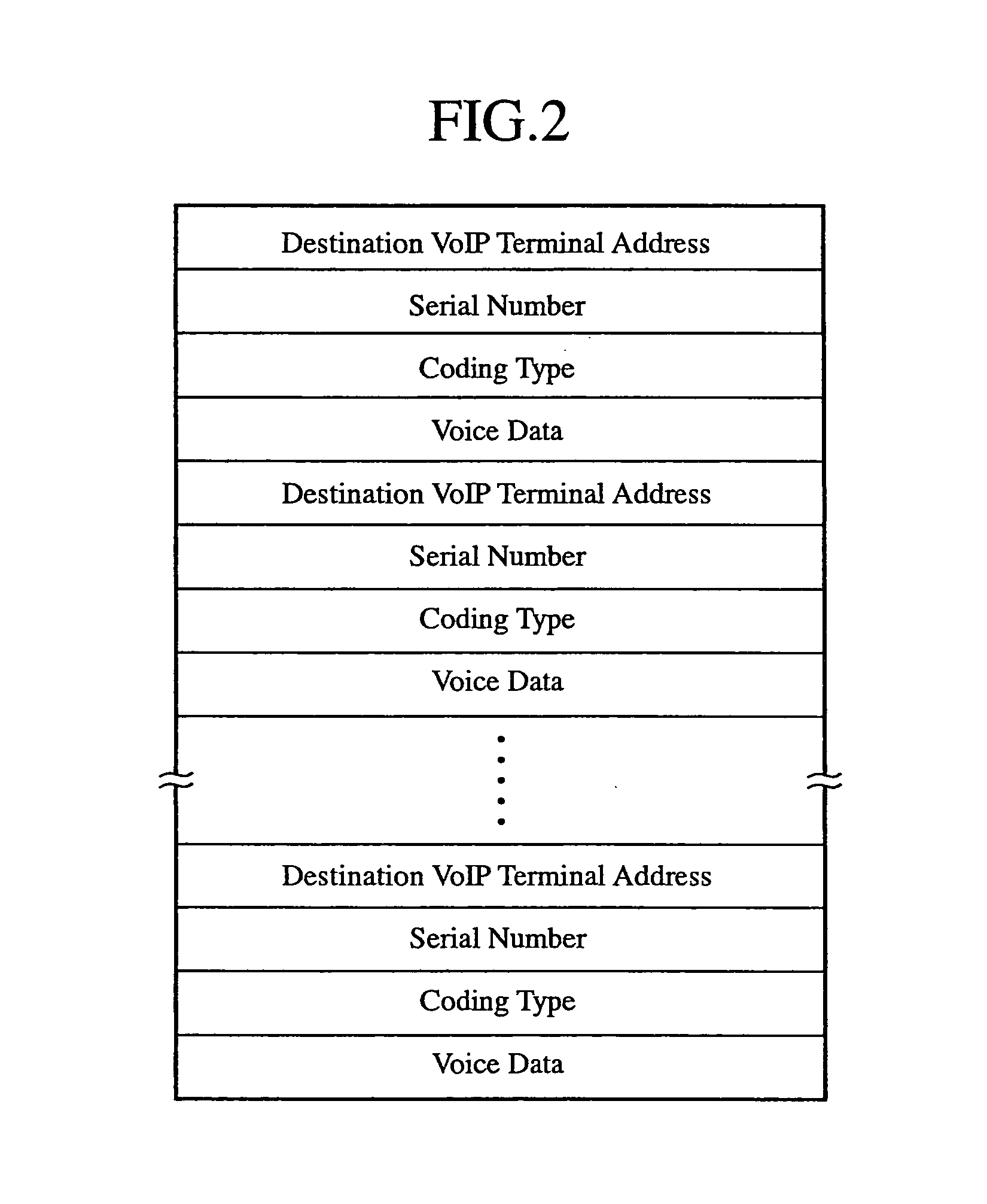
[0036] When receiving a connection request including a destination telephone number (for example, the telephone number of the VoIP terminal 4) from, for example, the VoIP terminal 1, a communication control apparatus 8 searches for an IP address corresponding to the destination telephone number, and then outputs the searched result to a multiplexing control apparatus 9. The multiplexing control apparatus 9 identifies both a multiplexing transmission apparatus 11 which manages the VoIP terminal 4 associated with the IP address searched for by the commu...
embodiment 2
[0077]FIG. 3 is a block diagram showing a packet communication system in accordance with embodiment 2 of the present invention. In the figure, the same reference numerals as shown in FIG. 1 denote the same components or like components, and therefore the explanation of the components will be omitted hereafter.
[0078] For example, when receiving a connection request including the telephone number of a VoIP terminal 2 from a VoIP terminal 1, a communication control apparatus 12 searches for the IP address of the VoIP terminal 2. When receiving a connection request including the telephone numbers of VoIP terminals 3 and 4 from the VoIP terminal 1, the communication control apparatus 12 searches for the IP address of a communication control apparatus 13 which manages the VoIP terminals 3 and 4. For example, when receiving a connection request including the telephone number of the VoIP terminal 4 from the VoIP terminal 3, the communication control apparatus 13 searches for the IP address...
embodiment 3
[0107] In above-mentioned embodiment 2, the multiplexing control apparatus 14 and 15 are installed in the local IP networks 5 and 6, respectively, as previously mentioned. As shown in FIG. 4, there may be a case in which no multiplexing control apparatus is installed in a local IP network 23. In FIG. 4, each of VoIP terminals 21 and 22 has the same structure as a VoIP terminal 1, a communication control apparatus 24 has the same structure as a communication control apparatus 12, and a multiplexing transmission apparatus 25 has the same structure as a multiplexing transmission apparatus 10.
[0108] In accordance with this embodiment 3, when the VoIP terminal 1 carries out communications of packets with the VoIP terminal 21 or 22, a multiplexing control apparatus 14 transfers a control packet (e.g., a connection request packet or a connection grant packet) which it has received from the VoIP terminal 1 to the VoIP terminal 21 or 22 without replacing the IP address of the VoIP terminal ...
PUM
 Abstract
Description
Claims
Application Information
 - R&D
- Intellectual Property
- Life Sciences
- Materials
- Tech Scout
- Unparalleled Data Quality
- Higher Quality Content
- 60% Fewer Hallucinations
Browse by: Latest US Patents, China's latest patents, Technical Efficacy Thesaurus, Application Domain, Technology Topic, Popular Technical Reports.
© 2025 PatSnap. All rights reserved.Legal|Privacy policy|Modern Slavery Act Transparency Statement|Sitemap|About US| Contact US: help@patsnap.com


