Battery module having the attachment members between battery cells

a battery module and battery cell technology, applied in the direction of batteries, flat cell grouping, sustainable manufacturing/processing, etc., can solve the problems of reducing the adhesive strength deteriorating the adhesiveness of the attachment member, and not maintaining the stacked structure of the battery cell, etc., to achieve high discharge voltage, high energy density, and high output stability

Inactive Publication Date: 2007-09-27
LG CHEM LTD
View PDF2 Cites 18 Cited by
  • Summary
  • Abstract
  • Description
  • Claims
  • Application Information

AI Technical Summary

Benefits of technology

[0010]As a result of a variety of extensive and intensive studies and experiments to solve the problems as described above, the inventors of the present invention have found that, when a battery module is manufactured using female- and male-type Velcro tapes as attachment members disposed between battery cells constituting the battery module, the battery cells are securely attached to each other by the coupling between the female- and male-type Velcro tapes, whereby the sliding of the battery cells due to external impacts is effectively prevented, the female- and male-type Velcro tapes are elastically deformed, when the external impacts are applied to the battery cells, to absorb the external impacts, it is possible for a coolant, such as air, to pass through the coupled Velcro tapes by virtue of the structural characteristics of the female- and male-type Velcro tapes, whereby the cooling efficiency of the battery module is improved, and the long-term use of the female- and male-type Velcro tapes is secured without the reduction of the attachment strength thereof, whereby the stacked structure of the battery module is stably maintained. The present invention has been completed based on these findings.
[0011]In accordance with the present invention, the above and other objects can be accomplished by the provision of a battery module constructed in a structure in which a plurality of plate-shaped battery cells are stacked one on another, wherein the battery module has attachment members interposed between the battery cells to prevent the battery cells from sliding due to external impacts and also to absorb the external impacts.
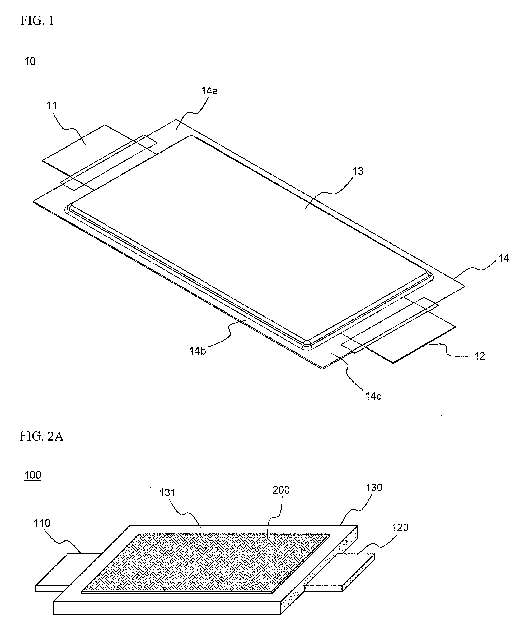
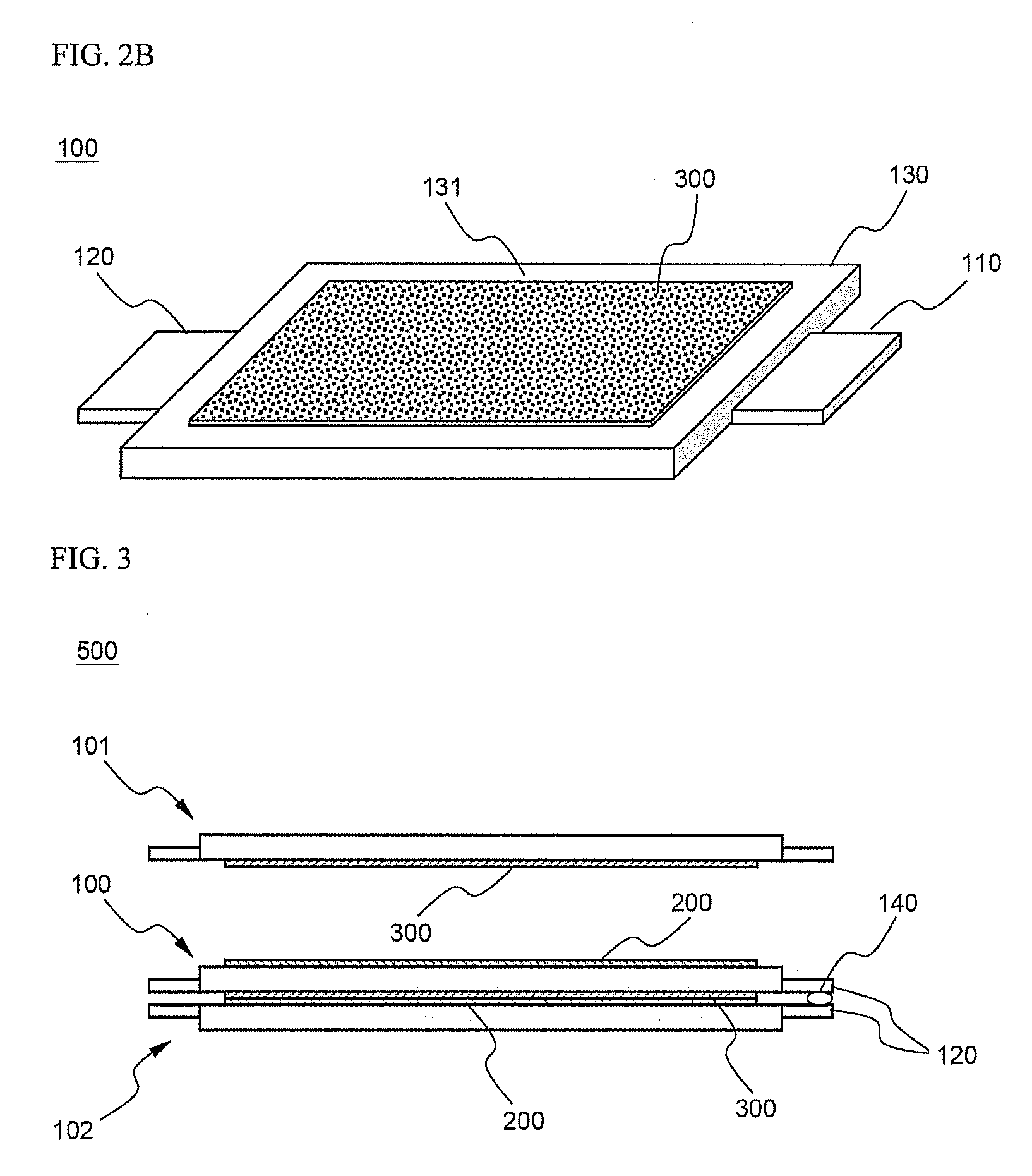
[0014]In a preferred embodiment, the attachment members, which serve to prevent the battery cells from sliding due to the external impacts and to absorb the external impacts, include a hook-shaped male-type Velcro tape and a loop-shaped female-type Velcro tape, which are attached to opposite major surfaces of the neighboring battery cells. For example, the male-type Velcro tape and the female-type Velcro tape may be attached to the lower major surface of one battery cell and the upper major surface of another battery cell. Specifically, the female-type Velcro tape attached to the upper major surface of one battery cell (a first battery cell) is coupled with the male-type Velcro tape attached to the lower major surface of another battery cell (a second battery cell) positioned on the first battery cell while the upper major surface of the first battery cell is opposite to the lower major surface of the second battery cell.
[0017]According to the present invention, a plurality of battery modules, each of which is coupled in the above-described structure, may be combined to provide a medium- or large-sized battery module having high output and large capacity. In this case, the coupling of each battery module may be accomplished in various manners in addition to the above description. The battery modules may be variably combined with each other depending desired output and capacity, and therefore, the applicability of the battery modules is very high.

Problems solved by technology

In the above-specified attachment members, however, the adhesiveness of the attachment members is deteriorated after the long-term use of the attachment members, whereby the adhesive strength of the attachment members is greatly reduced.
As a result, the stacked structure of the battery cells is not maintained.
Especially, the application of the attachment members to a medium- or large-sized battery module used as an energy source for electric vehicles and hybrid electric vehicles of which service life must be secured more than ten years or more is further limited.

Method used


Image

  • Battery module having the attachment members between battery cells
  • Battery module having the attachment members between battery cells
  • Battery module having the attachment members between battery cells

Examples


example 1

[0029]A mixture including 95 weight percent of LiCoO2, 2.5 weight percent of Super-P (a conducting agent), and 2.5 weight percent of PVdF (a coupling agent), as a cathode active material, was added to NMP (N-methyl-2-pyrrolidone), as a solvent, so as to manufacture cathode mixture slurry. Subsequently, the cathode mixture slurry was applied to aluminum foil, which was dried and pressed to manufacture cathodes. Similarly, a mixture including 95 weight percent of artificial graphite, 2.5 weight percent of Super-P (a conducting agent), and 2.5 weight percent of PVdF (a coupling agent), as an anode active material, was added to NMP, as a solvent, so as to manufacture anode mixture slurry. Subsequently, the anode mixture slurry was applied to copper foil, which was dried and pressed to manufacture anodes.

[0030]CellGuard™ was used as separators. The cathodes, the anodes, and the separators were sequentially stacked to construct an electrode assembly. The electrode assembly was mounted in ...

experimental example 1

[0033]The battery modules manufactured according to Example 1 and Comparative example 1 were put in a Z-axis vibration test to confirm the coupling between the batteries (a vibration test). The test result revealed that the battery module manufactured according to Example 1 exhibited little difference as compared to before the Z-axis vibration test, whereas the battery module manufactured according to Comparative example 1 exhibited positional deviation of approximately 10% between the respective batteries constituting the battery module as compared to before the Z-axis vibration test.

[0034]Also, the battery modules manufactured according to Example 1 and Comparative example 1 were put in high-temperature and high-humidity conditions, i.e., a temperature of 60° C. and a humidity of 90%, for seven weeks to confirm the coupling between the batteries (a weathering test). The test result revealed that the battery module manufactured according to Example 1 exhibited little difference as ...


PUM


Abstract

Disclosed herein is a battery module constructed in a structure in which a plurality of plate-shaped battery cells are stacked one on another. The battery module has attachment members interposed between the battery cells to prevent the battery cells from sliding due to external impacts and also to absorb the external impacts. The battery cells are securely attached to each other by the coupling between the attachment members, such as female- and male-type Velcro tapes. Consequently, the sliding of the battery cells due to external impacts is effectively prevented. Also, the female- and male-type Velcro tapes are elastically deformed, when the external impacts are applied to the battery cells, to absorb the external impacts. In addition, it is possible for a coolant, such as air, to pass through the coupled Velcro tapes by virtue of the structural characteristics of the female- and male-type Velcro tapes. Consequently, the cooling efficiency of the battery module is improved. Furthermore, the long-term use of the female- and male-type Velcro tapes is secured without the reduction of the attachment strength thereof, and therefore, the stacked structure of the battery module is stably maintained.

Description

FIELD OF THE INVENTION[0001]The present invention relates to a battery module having attachment members between battery cells, and, more particularly, to a battery module constructed in a structure in which a plurality of plate-shaped battery cells are stacked one on another wherein attachment members are interposed between the battery cells to prevent the battery cells from sliding due to external impacts and to absorb such external impacts.BACKGROUND OF THE INVENTION[0002]Recently, a secondary battery, which can be charged and discharged, has been widely used as an energy source for wireless mobile devices. Also, the secondary battery has attracted considerable attention as an energy source for electric vehicles (EV) and hybrid electric vehicles (HEV), which have been developed to solve problems, such as air pollution, caused by existing gasoline and diesel vehicles using fossil fuel.[0003]Small-sized mobile devices use one or several small-sized battery cells for each device. On ...

Claims


Application Information

Patent Timeline
IPC IPC(8): H01M6/46H01M10/05H01M10/0565H01M10/0585H01M50/211
CPCH01M10/0413H01M2/1016Y02E60/10Y02P70/50H01M50/211H01M10/647H01M10/625H01M10/613H01M10/653H01M10/6562H01M10/0525H01M2300/0082H01M2220/20H01M50/124H01M50/121H01M50/119
Inventor KIM, KIJAEKIM, MIN SU
Owner LG CHEM LTD
Why Eureka
Try Eureka