
System and method for laser speckle reduction

Inactive Publication Date: 2007-09-27
TEXAS INSTR INC
View PDF13 Cites 29 Cited by
  • Summary
  • Abstract
  • Description
  • Claims
  • Application Information

AI Technical Summary

Benefits of technology

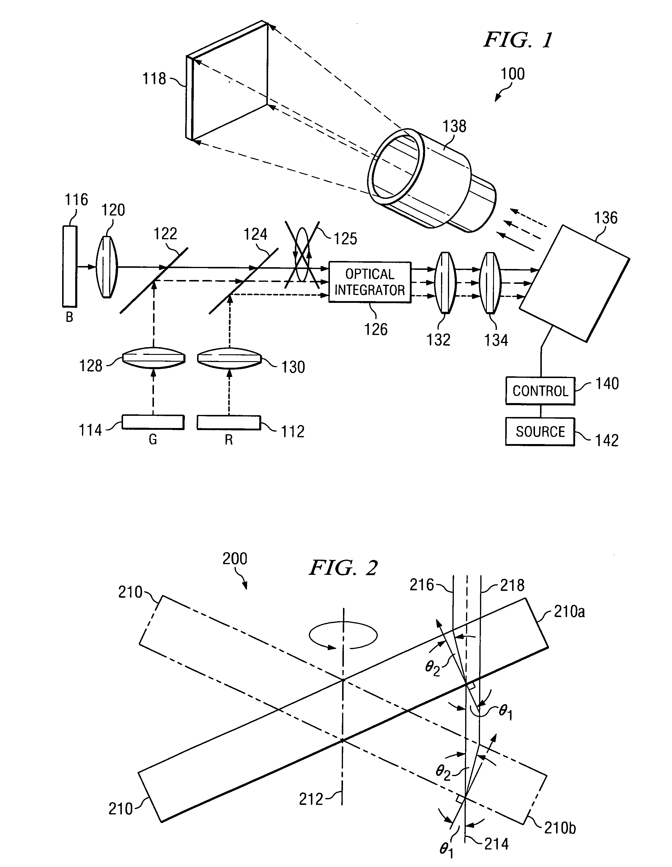
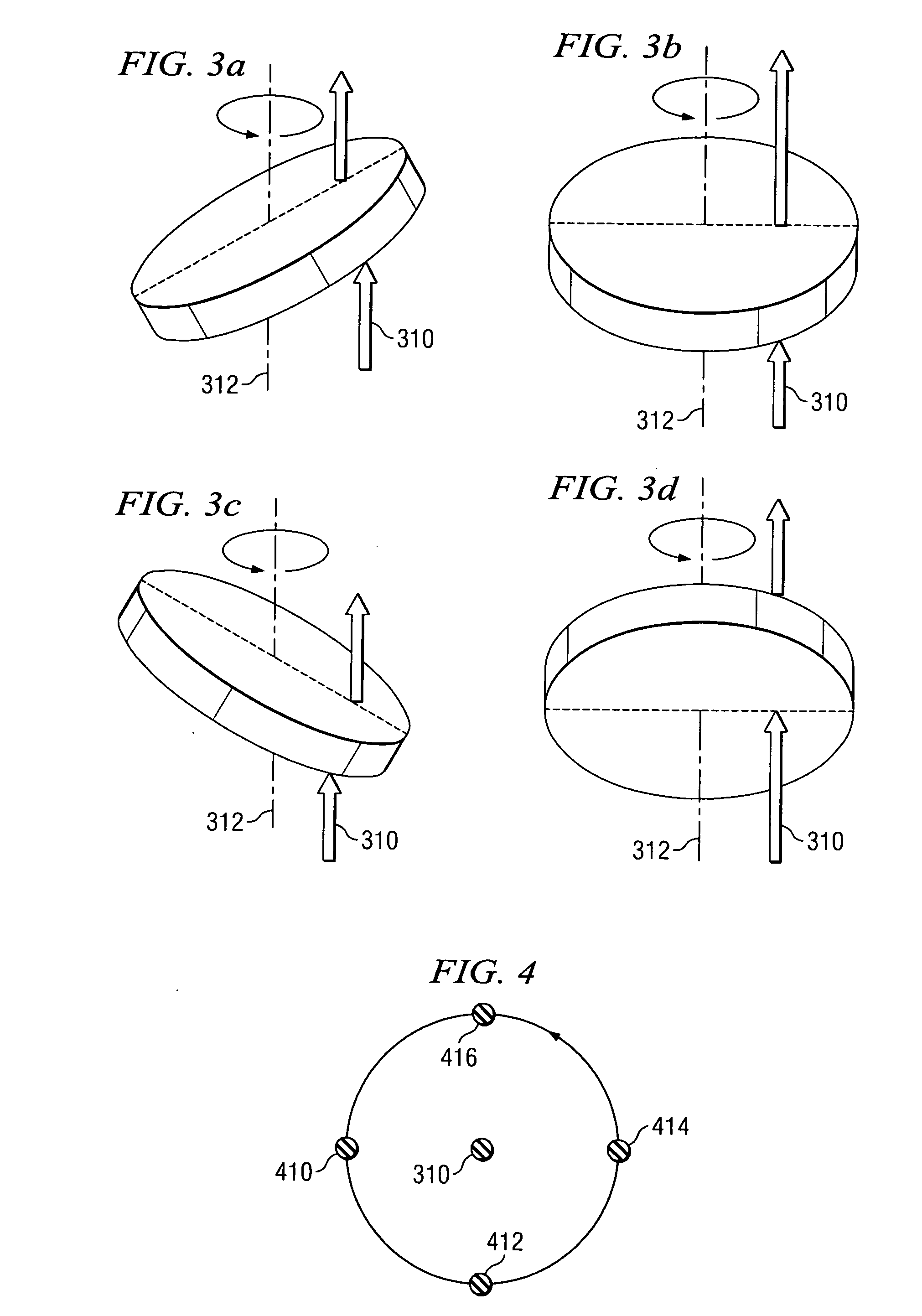
[0008] In an embodiment of the present invention, a rotating refracting device comprising a birefringent material is utilized to refract light beams from a coherent light source. The rotating refracting device causes the light beams from the coherent light source to be constantly moving, thereby reducing the speckle effect.
[0009] In an embodiment, the refracting device is a rotating circular shaped piece of birefringent material positioned such that a major surface of the birefringent material is normal to the light beam. In this embodiment, the coherent light is projected through the refracting device, and because the glass is rotating, the light beam moves in a pre-defined pattern, thereby reducing the speckle effect.

Problems solved by technology

While most lenses and mirrors appear to have a smooth surface, the surfaces are actually rough, consisting of ridges and valleys when magnified.
These diffuser systems, however, have several drawbacks.
One such drawback is that the diffuser significantly reduces the light energy.
In the field of projection systems, this drawback is particularly troublesome as the brightness and contrast that may be achieved by a projection system is one of the primary distinguishing factors.

Method used


Image

  • System and method for laser speckle reduction
  • System and method for laser speckle reduction
  • System and method for laser speckle reduction

Examples


Embodiment Construction

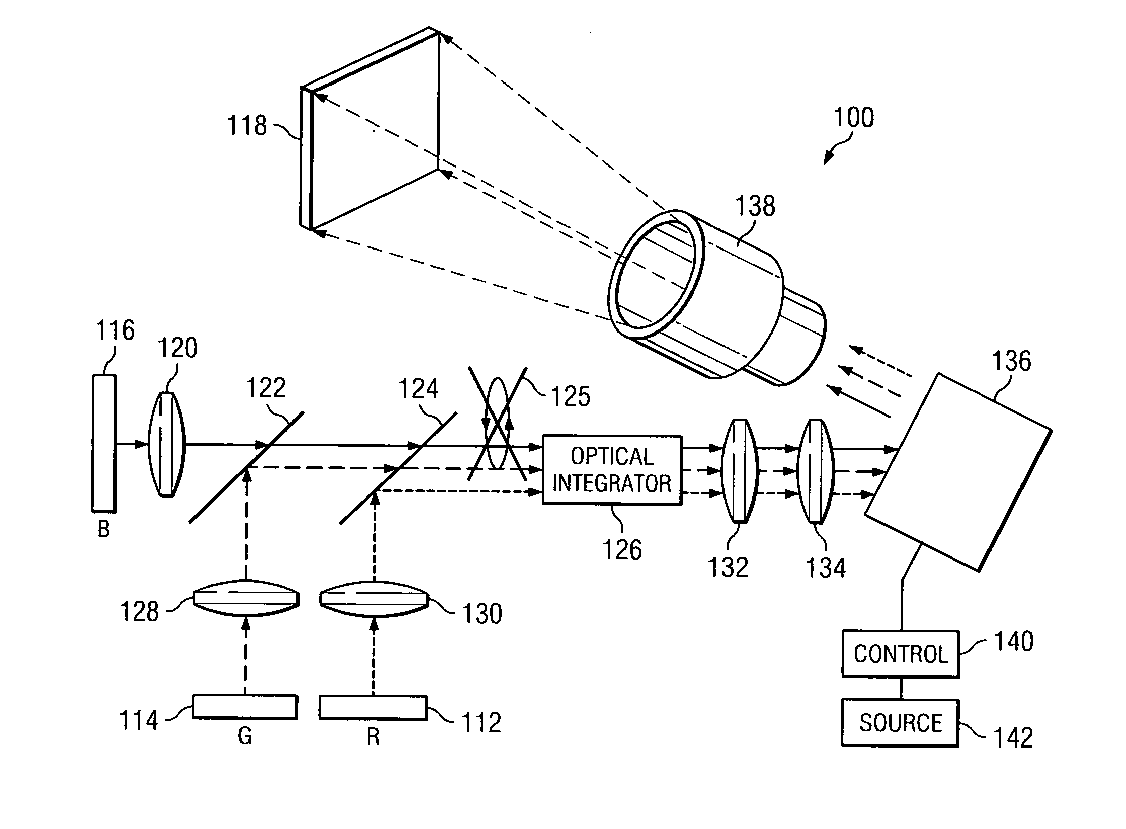
[0026] The making and using of the presently preferred embodiments are discussed in detail below. It should be appreciated, however, that the present invention provides many applicable inventive concepts that can be embodied in a wide variety of specific contexts. The specific embodiments discussed are merely illustrative of specific ways to make and use the invention, and do not limit the scope of the invention.

[0027] It should be noted that embodiments of the present invention are discussed in terms of a laser projection system for illustrative purposes only and that embodiments of the present invention may be utilized in any type of system, particularly systems using a monochromatic coherent light source, in which speckle may be a problem. Examples of systems in which embodiments of the present invention may be useful include projection systems, illumination systems, diagnostic systems, other systems using laser light, and the like.

[0028]FIG. 1 is a configuration diagram illust...


PUM


Abstract

A system and method for reducing or eliminating speckle when using a coherent light source is provided. A refracting device comprising a birefringent material is positioned such that the refracting device intercepts the coherent light. The refracting device rotates thereby causing the ordinary and / or extraordinary beams to move. The human eye integrates the movement of the beams, reducing or eliminating laser speckle. The refracting device may include one or more optical devices formed of a birefringent material. Wave plates, e.g., a ½ wave plate, may be inserted between optical devices to cause specific patterns to be generated. Multiple optical devices having a different orientation of the horizontal component of the optical axis may also be used to generate other patterns. Furthermore, the refracting device may include an optical device having multiple sections of differing horizontal components of the optical axis.

Description

CROSS-REFERENCE TO RELATED APPLICATIONS [0001] This application relates to the following co-pending and commonly assigned patent application: Ser. No. ______ (TI-61152), filed concurrently herewith, entitled System and Method for Laser Speckle Reduction, which application is are hereby incorporated herein by reference.TECHNICAL FIELD [0002] The present invention relates generally to laser systems and, more particularly, to reduction of speckle in laser systems. BACKGROUND [0003] Coherent light, such as light emitted by a laser, has increasingly been investigated for possible use in a wide variety of applications, including light sources for photography systems, projection systems, medical diagnostic systems, etc. Coherent light, generally, consists of light comprising in-phase light waves. As a result of the in-phase light waves, the use of coherent light may exhibit a phenomenon commonly referred to as speckle. [0004] Generally, speckle occurs when coherent light is reflected off o...

Claims


Application Information

Patent Timeline
IPC IPC(8): G02B5/30
CPCH04N9/3129G02B27/48
Inventor LEE, BENJAMIN LOWELL
Owner TEXAS INSTR INC
Learn More