Naphthacene derivative and organic electroluminescent device using the same
a technology of organic electroluminescent devices and naphthacene, which is applied in the direction of discharge tube luminescnet screens, organic chemistry, natural mineral layered products, etc., can solve the problems of insufficient halftime luminance of about 150 hours, high applied voltage, and inability to achieve practical luminous efficiency and lifetime. , the effect of long life and excellent color purity
- Summary
- Abstract
- Description
- Claims
- Application Information
AI Technical Summary
Benefits of technology
Problems solved by technology
Method used
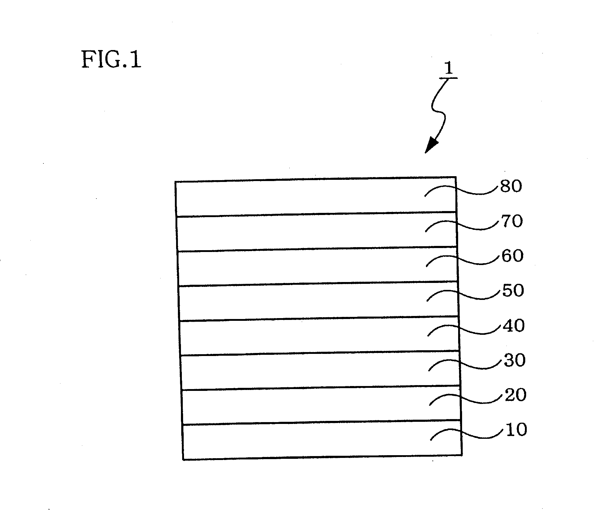
Image

Examples
synthesis example 1
[0152]
(1) Synthesis of Intermediate (A-1a)
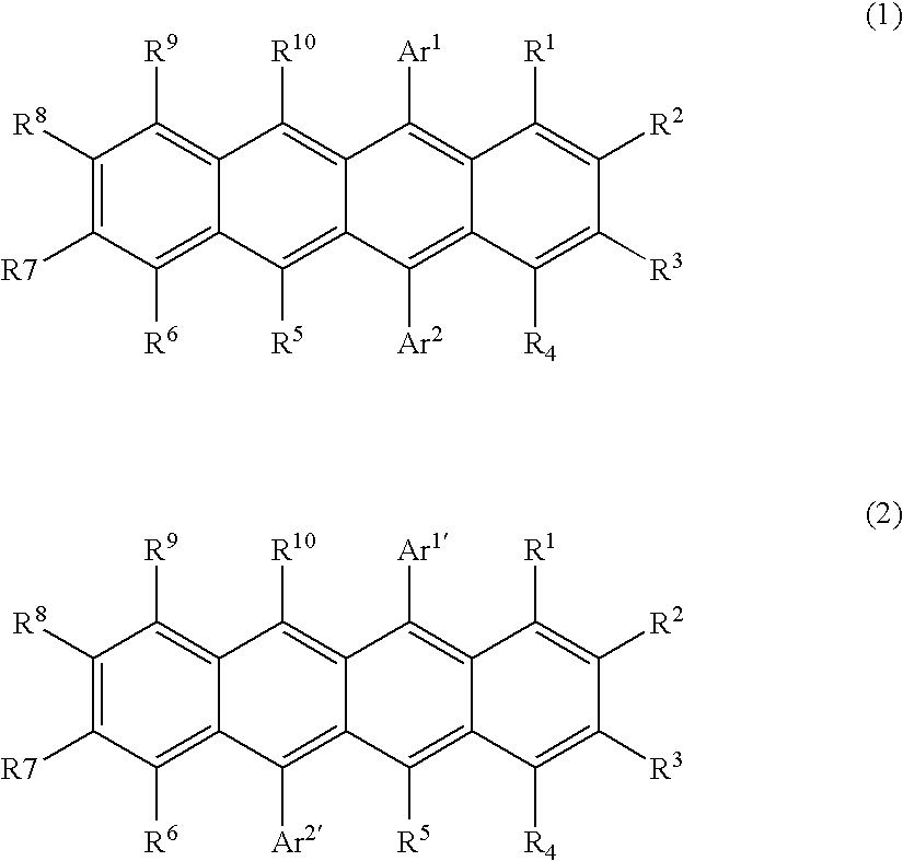
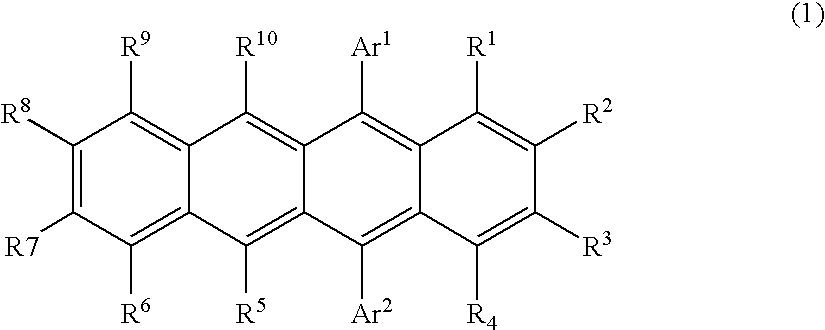
[0153] 5.5 g of 2,4,6-triphenyliodobenzene was dissolved in 40 ml of toluene. After adding 13 mL of diethyl ether, the resultant mixture was cooled to −55° C. 8 mL of a 1.6 M solution of n-butyl lithium in n-hexane was added, and the resultant mixture was stirred for one hour. 2.6 g of 5,12-naphthacene quinone powder was added, and then the resultant mixture was allowed to react for three hours with gradually increasing the temperature to 0° C. The reaction was stopped by adding 20 mL of methanol, and the solid produced was recovered by filtering, followed by washing with methanol. The resultant solid was purified by silica-gel column chromatography to obtain 5.7 g (yield: 99%) of pale yellow powder of an intended intermediate (A-1a).
(2) Synthesis of Intermediate (A-1b)
[0154] 2.8 g of the intermediate (A-1a) was dissolved in 30 mL of tetrahydrofuran, and 15 mL of a 1 M solution of phenyl magnesium bromide in tetrahydrofuran was dripped ...
synthesis example 2
[0158]
(1) Synthesis of Intermediate (A-3b)
[0159] 7.4 g of 2,4-diphenyliodobenzene was dissolved in 45 ml of toluene. After adding 15 mL of diethyl ether, the resultant mixture was cooled to −55° C. 13 mL of a 1.6 M solution of n-butyl lithium in n-hexane was added, and the resultant mixture was stirred for one hour. 1.9 g of 5,11-naphthacene quinone powder was added, and then the resultant mixture was allowed to react for three hours with gradually increasing the temperature to 0° C. The reaction was stopped by adding 20 mL of methanol, and the solid produced was recovered by filtering, followed by washing with methanol. After washing the resultant solid with toluene under heated reflux, the resultant solid was dried under vacuum to obtain 3.3 g (yield: 60%) of pale yellow powder of an intended intermediate (A-3b).
(2) Synthesis of Compound A-3
[0160] 80 mL of tetrahydrofuran was added to 3.3 g of the intermediate (A-3b) and the mixture was heated to about 40° C. to dissolve the ...
synthesis example 3
[0161]
(1) Synthesis of Intermediate (A-4-a)
[0162] 5.5 g of 2,4,6-triphenyliodobenzene was dissolved in 40 ml of toluene. After adding 13 mL of diethyl ether, the resultant mixture was cooled to −55° C. 8 mL of a 1.6 M solution of n-butyl lithium in n-hexane was added, and the resultant mixture was stirred for one hour. 2.6 g of 5,11-naphthacene quinone powder was added, and then the resultant mixture was allowed to react for three hours with gradually increasing the temperature to 0° C. The reaction was stopped by adding 20 mL of methanol, and the solid produced was recovered by filtering, followed by washing with methanol. The resultant solid was purified by silica-gel column chromatography to obtain 5.7 g (yield: 99%) of pale yellow powder of an intended intermediate (A-4-a).
(2) Synthesis of Intermediate (A-4-b)
[0163] 2.8 g of the intermediate (A-4-a) was dissolved in 30 mL of tetrahydrofuran, and 15 mL of a 1 M solution of phenyl magnesium bromide in tetrahydrofuran was drip...
PUM
| Property | Measurement | Unit |
|---|---|---|
| Color | aaaaa | aaaaa |
| Concentration | aaaaa | aaaaa |
| Luminescence | aaaaa | aaaaa |
Abstract
Description
Claims
Application Information
 - R&D
- Intellectual Property
- Life Sciences
- Materials
- Tech Scout
- Unparalleled Data Quality
- Higher Quality Content
- 60% Fewer Hallucinations
Browse by: Latest US Patents, China's latest patents, Technical Efficacy Thesaurus, Application Domain, Technology Topic, Popular Technical Reports.
© 2025 PatSnap. All rights reserved.Legal|Privacy policy|Modern Slavery Act Transparency Statement|Sitemap|About US| Contact US: help@patsnap.com