Control device for engine valve and control system for engine

Inactive Publication Date: 2007-09-27
DENSO CORP
View PDF2 Cites 4 Cited by
  • Summary
  • Abstract
  • Description
  • Claims
  • Application Information

AI Technical Summary

Benefits of technology

[0009]It is an object of the present invention to provide a control device for an engine valve and a control system for an engine valve which change a rotational phase difference of a cam shaft relative to a crank shaft to adjust operating timing of the engine valve, thereby accurately maintaining controllability in the rotational phase difference while restricting an increase in adaptation work at the time of controlling operating timing of the engine valve.
[0014]According to the above arrangement, the holding learning value is altered only by the specified value on condition that the operational signal for holding the rotational phase difference is assumed to change. Therefore, even if the operating signal is altered to a side of increasing a difference between the actual value of the rotational phase difference and the target value at the time of changing the actual value of the rotational phase difference for follow-up to the target value, this alteration can be compensated for. As a result, controllability of the rotational phase difference can be accurately maintained with easy adaptation of adapting the predetermined value.

Problems solved by technology

This change invites deterioration in controllability of the feedback control.
In this case, however, since the holding learning value is required for each region, a great deal of work is to be required for adaptation of the holding learning value.

Method used


Image

  • Control device for engine valve and control system for engine
  • Control device for engine valve and control system for engine
  • Control device for engine valve and control system for engine

Examples


first embodiment

[0026]A first embodiment where a control device and a control system for an engine valve according to the present invention are applied to a gasoline engine will be hereinafter described with reference to the accompanying drawings.

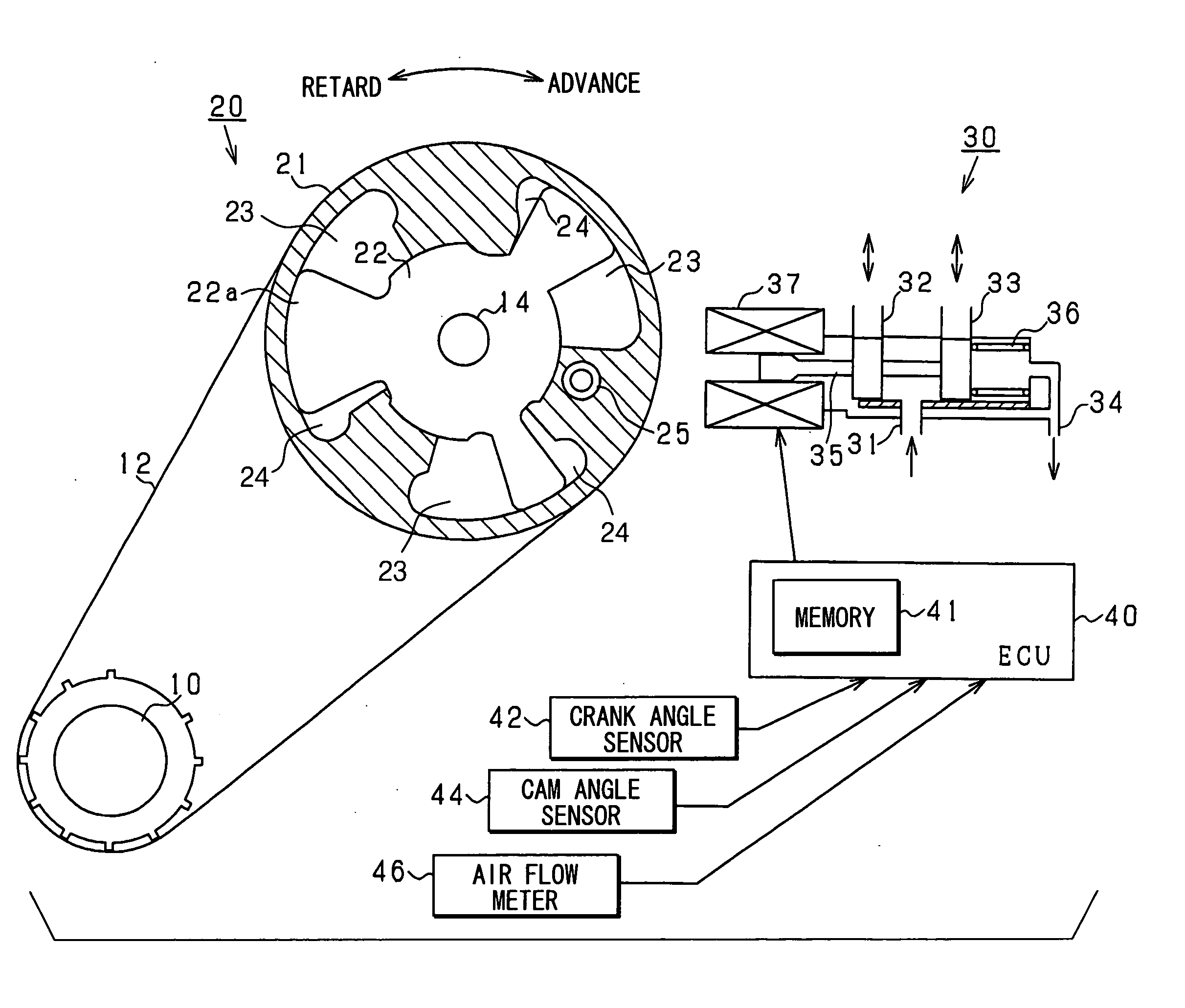
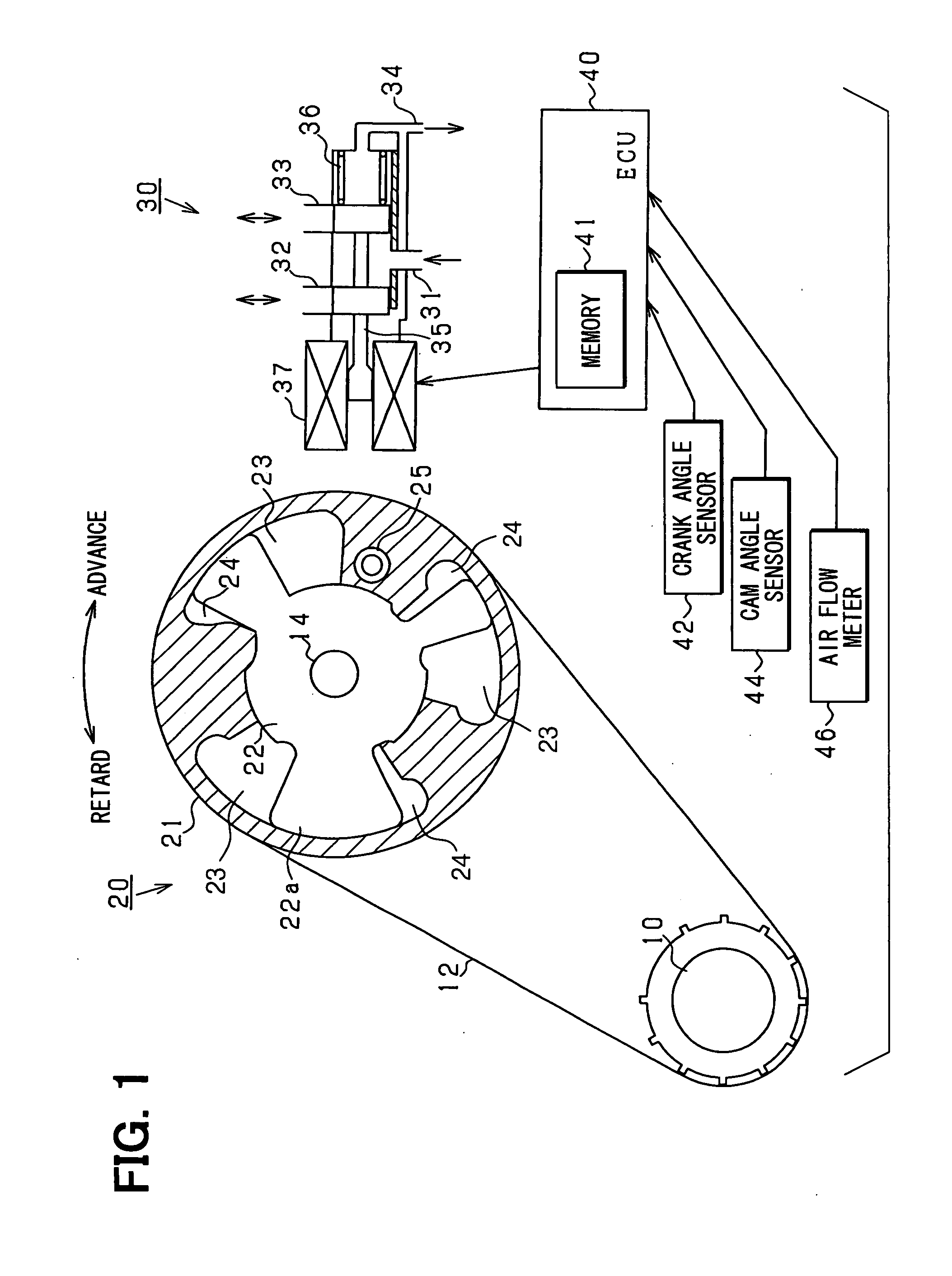
[0027]FIG. 1 shows an entire structure of a control system for an engine valve in the first embodiment.

[0028]As shown in FIG. 1, power of crankshaft 10 is transmitted through a belt 12 and a variable valve timing mechanism 20 to a camshaft 14. The variable valve timing mechanism 20 is provided with a first rotational element 21 connected mechanically to the crank shaft 10 and a second rotational element 22 connected mechanically to the cam shaft 14. In addition, in the first embodiment, the second rotational element 22 is provided with a plurality of projections 22a and also is accommodated in the first rotational element 21. Further, a retard chamber 23 and an advance chamber 24 are defined between the projection 22a of the second rotational element 22 an...

second embodiment

[0063]Mainly a difference of the second embodiment from the first embodiment will be hereinafter described with reference to the accompanying drawings.

[0064]FIG. 6 shows a routine of control for a rotational phase difference between a camshaft and a crankshaft in the second embodiment. This routine is repeatedly executed for example, in a predetermined cycle by the ECU 40. The processes in FIG. 6 which are the same as those in FIG. 3 are referred to as the same step numbers for convenience.

[0065]In the second embodiment, when it is determined in step S28 shown in FIG. 3 described before that the absolute value of the changing amount in the target advance value VVTa is more than the predetermined value γ, the HLV is variably set in response to the changing amount in the target advance value VVTa. This is because since the changing amount of the target advance value VVTa is defined by a changing degree of an engine operating condition, the changing degree of the engine operating condi...

third embodiment

[0068]Mainly a difference of the third embodiment from the second embodiment will be hereinafter described with reference to the accompanying drawings.

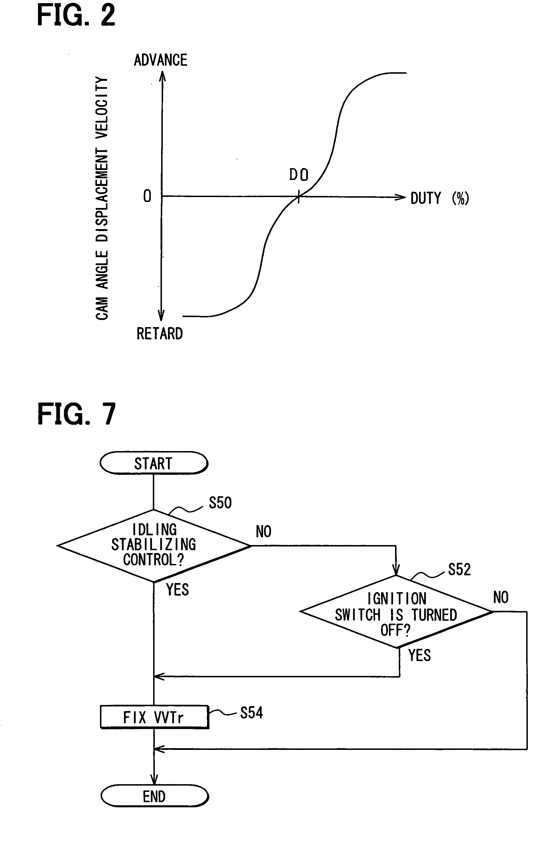
[0069]At the operating of the engine, the target advance value VVTa is basically calculated in step S10 previously shown in FIG. 6 and the actual advance value VVTr is controlled to follow the target advance value VVTa. However, the control to the target advance value VVTa is not always performed in fact and as shown in FIG. 7, there is a case where the actual advance value VVTr is fixed to the maximum retard position.

[0070]FIG. 7 shows a routine of control for an actual advance value VVTr in the third embodiment. This routine is repeatedly executed for example, in a predetermined cycle by the ECU 40.

[0071]In a series of processes in this routine, an actual advance value VVTr is controlled to be fixed to the maximum retard position when an idling stabilizing control is performed (step S50: YES) and an ignition switch is switched to be...


PUM


Abstract

A rotational phase difference of a camshaft relative to a crankshaft in a variable valve timing mechanism is controlled by an operation of an oil control valve. That is, in the oil control valve, there is outputted an operational signal which is defined by adding a feedback correction amount corresponding to a difference between an actual value and a target value of the rotational phase difference, to a holding learning value as the operational signal for holding the rotational phase difference. The holding learning value is altered only by a specified value on condition that the operational signal for holding the rotational phase difference is assumed to change.

Description

CROSS REFERENCE TO RELATED APPLICATION[0001]This application is based on Japanese Patent Application No. 2006-84662 filed on Mar. 27, 2006, the disclosure of which is incorporated herein by reference.FIELD OF THE INVENTION[0002]The present invention relates to a control device for an engine valve and a control system for an engine valve which feedback-control a rotational phase difference of a camshaft relative to a crankshaft to obtain a target valve timing.BACKGROUND OF THE INVENTION[0003]A rotational phase difference-adjusting device varies a rotational phase difference of a camshaft relative to a crankshaft in an internal combustion engine for adjusting operating timing of an engine valve. The rotational phase difference-adjusting device is provided with a variable valve timing mechanism and an oil control valve. The variable valve timing mechanism is usually provided with rotational elements connected respectively to the crankshaft and the camshaft. An advance chamber for advan...

Claims


Application Information

Patent Timeline
IPC IPC(8): F01L1/34
CPCF01L1/3442Y10T74/1584F01L2800/00F01L2001/34426
Inventor KADOWAKI, HISASHI
Owner DENSO CORP
Why Eureka
Try Eureka