Method for switching a hydraulic pressure intensifier

A hydraulic and multiplier technology, which is applied in the direction of fluid pressure actuators, servo motors, servo meter circuits, etc., can solve the problems of dependence, complexity, and difficult adjustment of accurate time points, etc., to achieve weakened mechanical friction, simple structure, and time-saving optimized effect

Inactive Publication Date: 2005-08-17
TOX PRESSOTECHNIK GMBH & CO KG
View PDF1 Cites 0 Cited by
  • Summary
  • Abstract
  • Description
  • Claims
  • Application Information

AI Technical Summary

Problems solved by technology

A major problem when using this device is that the exact timing of the switching process is relatively difficult to adjust, since the switching time is determined by the diving timing of the diving piston, which in turn depends on the engagement of the pneumatic drive
The problem, which does not arise until the transition from reservoir pressure to high pressure needs to be done accurately, is complex and mostly not satisfactorily resolved

Method used


Image

  • Method for switching a hydraulic pressure intensifier
  • Method for switching a hydraulic pressure intensifier
  • Method for switching a hydraulic pressure intensifier

Examples


Embodiment Construction

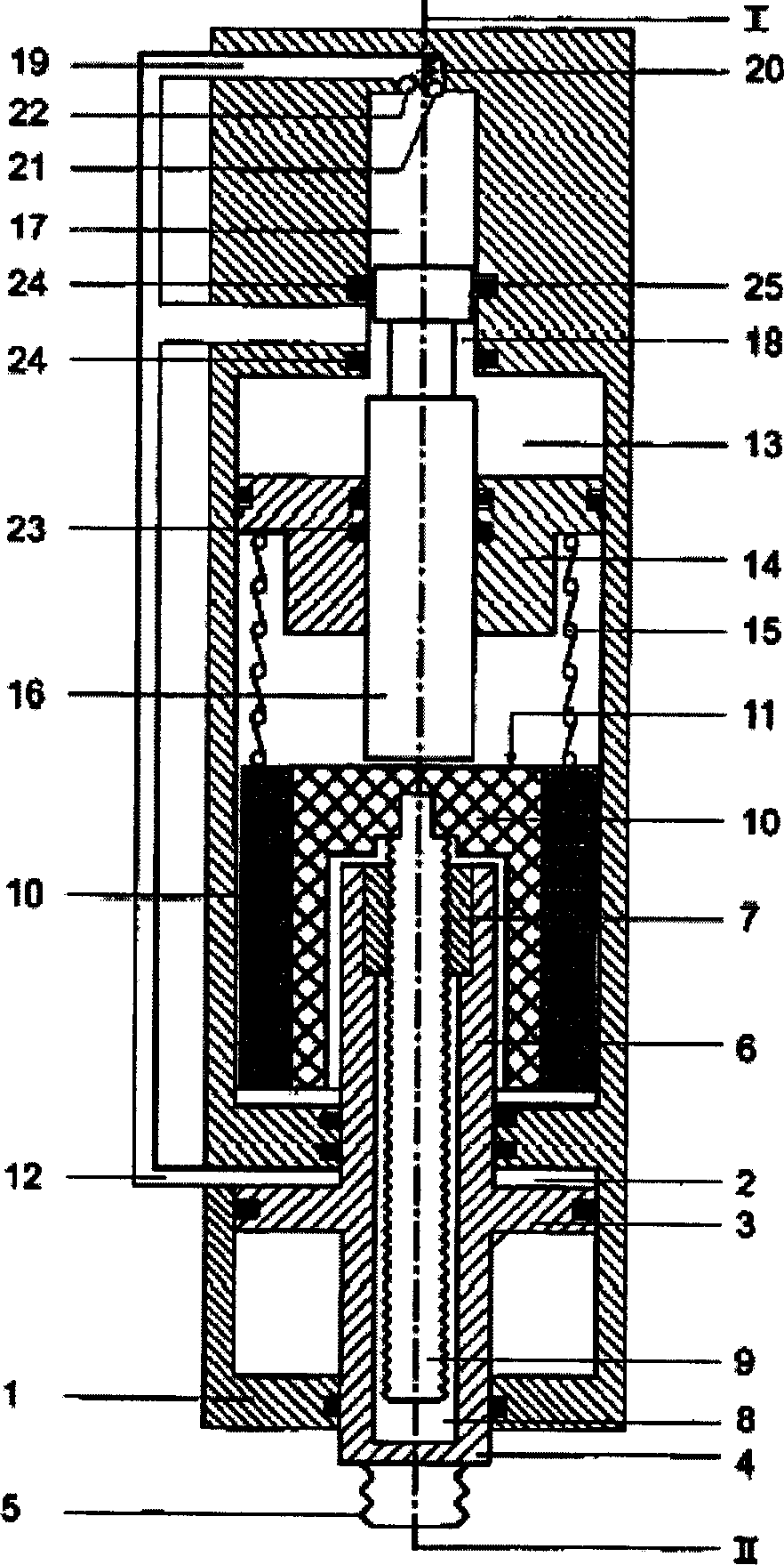
[0025] exist figure 1 The hydraulic pressure multiplier given as a first example in , is a relatively small device in a compact component form. In this case, the axially displaceable part is arranged along the longitudinal axis I. In the housing 1 there is radially sealed a working piston 3 which is axially displaceable in a cylinder-like working chamber 2 . On the working piston 3 a piston rod 4 is mounted, the free end of which has a thread 5 for fastening a tool and protrudes out of the housing 1 for tool control. Working piston 3 is secured against self-rotation by means not shown. In addition, the side of the working piston 3 facing away from the piston rod 4 is equipped with a sleeve-like section 6 , in which a nut 7 is mounted in a rotationally coupled manner, which connects the working piston 3 , the piston rod 4 and the center in the section 6 . The blind hole 8 is closed.

[0026] Inside the nut 7 runs a threaded spindle 9 which in turn is connected in rotation w...


PUM


Abstract

The invention relates to a method for switching a machine tool from rapid travel to working travel and to a hydraulic pressure intensifier, especially for carrying out the inventive method. According to the invention, the machine tool is automatically switched from rapid travel to working travel when a defined counter-force occurs.

Description

Background technique [0001] The invention relates to a method for switching from rapid travel to working travel in a machine tool, of the type described in the independent claims. By using this method in machine tools and hydraulic pressure multipliers, a wide variety of different types of tools can be controlled, as long as it is necessary to include a fast stroke to advance the tool as quickly as possible to the place to be processed On the workpiece, high machining stress is then applied, and the machining of the tool to the workpiece is completed with a relatively small working stroke. [0002] Furthermore, the invention relates to a hydraulic pressure multiplier for carrying out the method, in particular of the type as claimed in the dependent claim 6 . In principle, for fast strokes and the low drive force required to drive the working piston therein, a relatively low pressure in the storage chamber acting on the working piston, or a relatively low actuating Force is n...

Claims


Application Information

Patent Timeline
Patent Type & Authority Applications(China)
IPC IPC(8): F15B11/032
CPCF15B2211/625F15B2211/212F15B2211/775F15B11/0325
Inventor E・拉普
Owner TOX PRESSOTECHNIK GMBH & CO KG
Why Eureka
Try Eureka