Limiting mechanism for mobile door lock
A technology of limiting mechanism and door lock, applied in the field of sliding door locks, can solve the problems of heavy and stiff hand, complex structure, easy wear, etc., and achieve the effects of reducing mechanical friction, good hand feeling, and simple structure inside the lock
- Summary
- Abstract
- Description
- Claims
- Application Information
AI Technical Summary
Problems solved by technology
Method used
Image

Examples
Embodiment 1
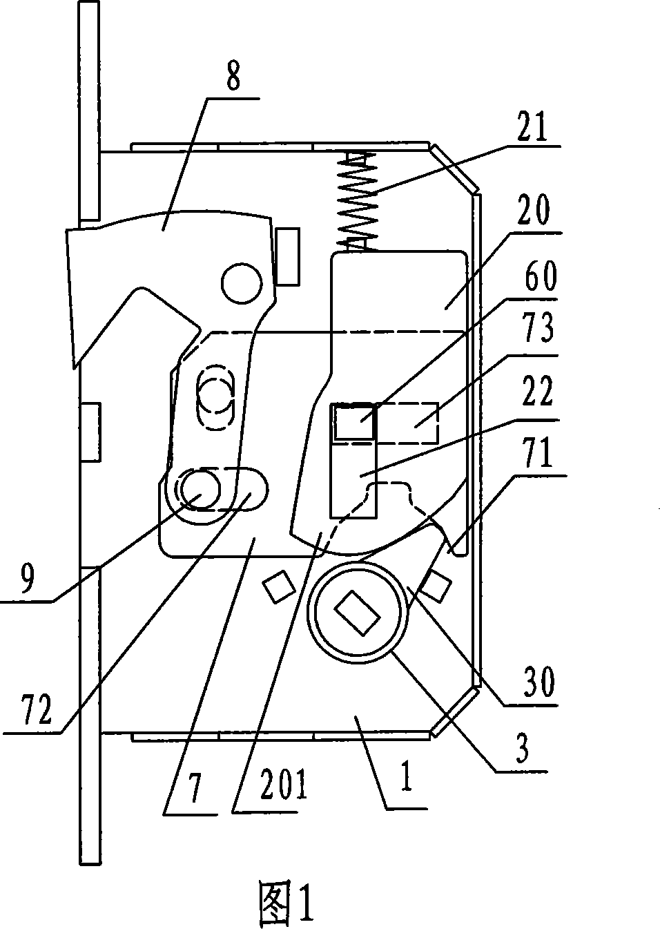
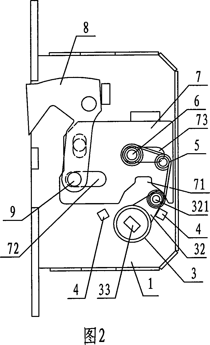
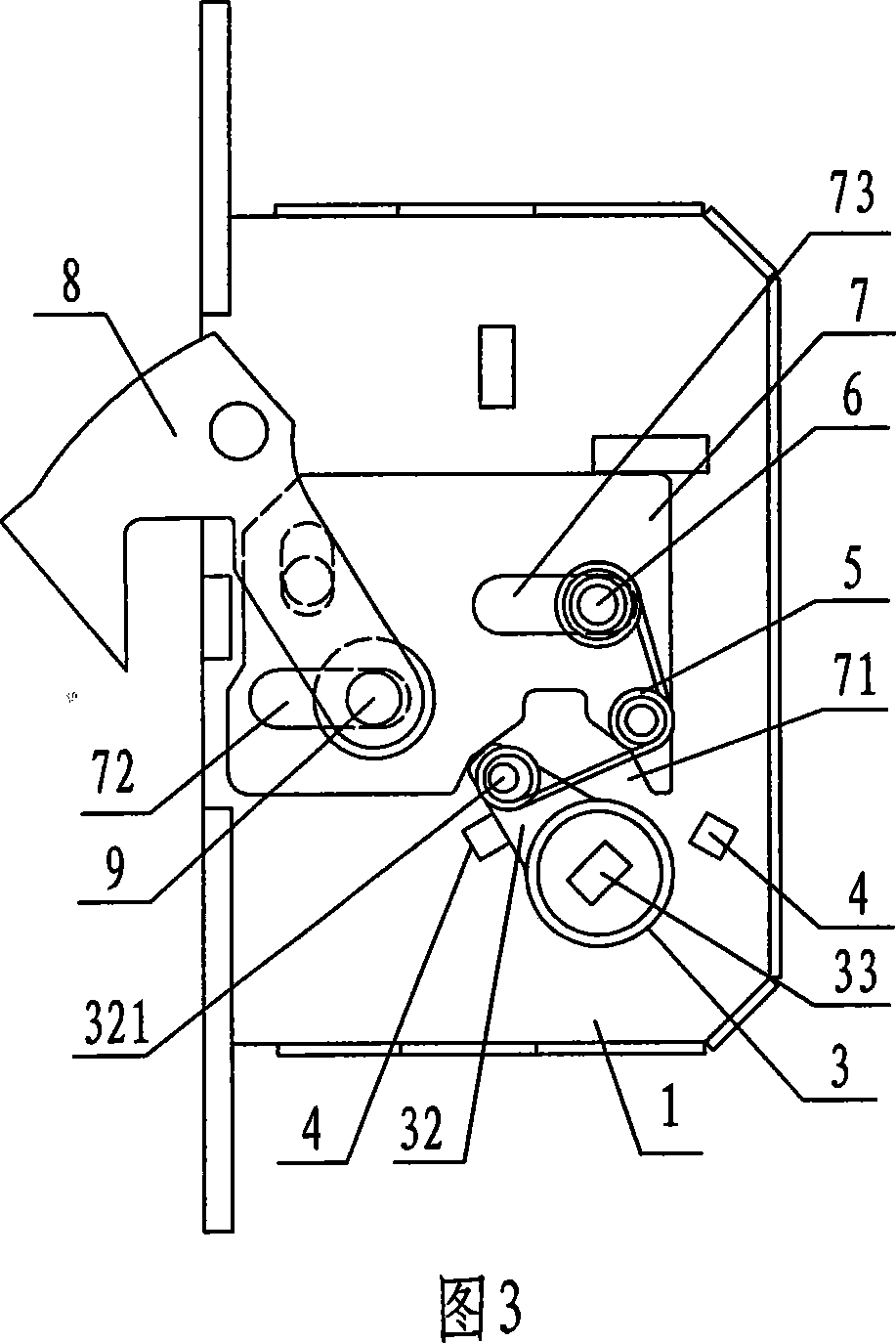
[0026] As shown in Figures 2 and 3, a position-limiting mechanism for a sliding door lock includes a lock housing 1, a toggle wheel 3 rotatably fixed in the lock housing 1, and a toggle wheel 3 slidably fixed in the lock housing. The positioning plate 7 in the shell 1; the side part of the toggle wheel 3 is provided with a toggle arm 32, the toggle arm 32 is provided with a protruding shaft 321, the side of the positioning plate 7 is provided with a fork 71, and the toggle arm 32 Stretching into the fork 71 forms a toggle connection.
[0027] The lock housing 1 also includes three rings of special-shaped springs 5 and a spring positioning shaft 6 fixed in the lock housing. It is connected to the spring positioning shaft 6, so that the three-circle special-shaped spring 5 directly constitutes a position-limiting mechanism for the toggle wheel 3 and further for the positioning plate 7.
[0028] As shown in Figures 2 and 3, other mechanisms of the sliding door lock that cooper...
Embodiment 2
[0037] As shown in Figure 4, a position-limiting mechanism of a sliding door lock includes a lock case 1, a toggle wheel 3 rotatably fixed in the lock case 1, and a toggle wheel 3 slidably connected in the lock case 1. The positioning plate 7 inside; the upper side of the toggle wheel 3 is provided with a toggle arm 32, and the toggle arm 32 is provided with a protruding shaft 321; the side of the toggle wheel 3 is also provided with a tooth groove 34, and the positioning A side tooth groove 77 is provided on the side of the plate 7 , and the toggle wheel 3 is connected to the positioning plate 7 through the meshing mode of the wheel tooth groove 34 and the side tooth groove 77 .
[0038] The lock housing 1 also includes three rings of special-shaped springs 5 and a spring positioning shaft 6 fixed in the lock housing. It is connected to the spring positioning shaft 6, so that the three-circle special-shaped spring 5 directly constitutes a position-limiting mechanism for the...
Embodiment 3
[0042] As shown in Figure 5, a position-limiting mechanism of a sliding door lock includes a lock case 1, a toggle wheel 3 rotatably fixed in the lock case 1, and a toggle wheel 3 slidably connected in the lock case 1. The positioning plate 7 inside; the side portion of the toggle wheel 3 is also provided with a tooth groove 34, and the side portion of the positioning plate 7 is provided with a side tooth groove 77, and the toggle wheel 3 and the positioning plate 7 pass through The gear tooth groove 34 and the side tooth groove 77 are in transmission connection in a meshing manner.
[0043] The lock housing 1 also includes three rings of special-shaped springs 5 and a spring positioning shaft 6 fixed in the lock housing. The head end of the three rings of special-shaped springs 5 is fixedly connected to the positioning plate 7, and the tail end is fixed to the said positioning plate 7. On the spring positioning shaft 6, the three-circle special-shaped spring 5 directly co...
PUM
 Abstract
Description
Claims
Application Information
 - R&D
- Intellectual Property
- Life Sciences
- Materials
- Tech Scout
- Unparalleled Data Quality
- Higher Quality Content
- 60% Fewer Hallucinations
Browse by: Latest US Patents, China's latest patents, Technical Efficacy Thesaurus, Application Domain, Technology Topic, Popular Technical Reports.
© 2025 PatSnap. All rights reserved.Legal|Privacy policy|Modern Slavery Act Transparency Statement|Sitemap|About US| Contact US: help@patsnap.com