Smart flow sharing system

a technology of flow sharing and hydraulic valve, applied in the direction of fluid couplings, servomotors, couplings, etc., can solve the problems of power used to pump the unused hydraulic fluid flow, the effect of loss, and different functions that require more hydraulic pressure, etc., and achieve the effect of precise control

Active Publication Date: 2014-08-19
PARKER INTANGIBLES LLC
View PDF22 Cites 0 Cited by
  • Summary
  • Abstract
  • Description
  • Claims
  • Application Information

AI Technical Summary

Benefits of technology

[0038]Still another object of the embodiments of the smart flow sharing system invention described herein is to achieve the above objects without the addition of complex and difficult to maintain components, without the addition of expensive additional components or systems, and in a manner that is not cost-prohibitive, but rather in a manner that is cost-efficient.
[0040]In the described embodiments of the present invention, an improved hydraulic valve system, called a smart flow sharing system, is provided, wherein hydraulic fluid flow under pressure is provided on an automatically prioritized basis to the more demanding hydraulic functions. This prioritization is accomplished without the addition of complex components or expensive extra equipment. Instead, the smart flow sharing system provides a uniquely designed hydraulic system using more than one (preferably two) fixed displacement pumps rather than one, combined with an additional spool, which directs hydraulic fluid flow / pressure in a manner such that if more than one of the more demanding hydraulic functions are simultaneously activated, then one of those more demanding hydraulic functions receives, separately, the hydraulic fluid flow output from the first fixed displacement pump, and the other demanding hydraulic function receives the separate hydraulic fluid flow output from the second fixed displacement pump. On the other hand, if only one of the two more demanding hydraulic functions is activated, then that hydraulic function receives the hydraulic fluid flow output from both the first and second fixed displacement pumps.
[0041]As a result, the shortcomings of the prior art are overcome. The provision of hydraulic fluid flow from two fixed displacement pumps to a single demanding hydraulic function results in more precise controllability and quicker equipment speed, permitting even less experienced equipment operators to achieve superior performance. On the other hand, when the two most demanding hydraulic functions are activated at the same time, the automatic prioritization of hydraulic fluid flow so that each of the two demanding hydraulic functions automatically receives hydraulic fluid output from its own separate dedicated fixed displacement pump eliminates complicated and meticulous metering of hydraulic fluid flow, once again enabling even inexperienced operators to achieve fast equipment movement and precise control of the equipment. Furthermore, the smart flow sharing system accomplishes this result without resorting to complex, difficult to maintain hydraulic systems or expensive additional components. The result is a cost-effective and maintenance friendly hydraulic system that is superior to prior art options.

Problems solved by technology

(The power used to pump the unused hydraulic fluid flow is, in that case, effectively a loss).
Additionally, different movements of functions require more hydraulic pressure than others.
Moreover, even similar movements of the same function may require different hydraulic pressures depending upon different conditions.
Consequently, in order for an operator to control both functions (fork lifting and fork extension), the operator is required to utilize the activator (e.g., joystick 182) in a manner to meticulously meter the flow of hydraulic fluid through the extension function (block E of valve 114) creating a power loss.
Furthermore, the controllability that can be attained using that technique is not very high and depends considerably on the ability and skills of the operator, because the two hydraulic pressures to be delivered to the functions are dependent on the load and fork position (extension, height, and angle), which change.
Such a system, however, is much more complicated and much more costly, because it requires the introduction of a variable displacement pump and flow / pressure compensators.
Consequently, this potential alternative has been largely deemed unacceptable as being more difficult to maintain and somewhat cost prohibitive.

Method used


Image

  • Smart flow sharing system
  • Smart flow sharing system
  • Smart flow sharing system

Examples


Embodiment Construction

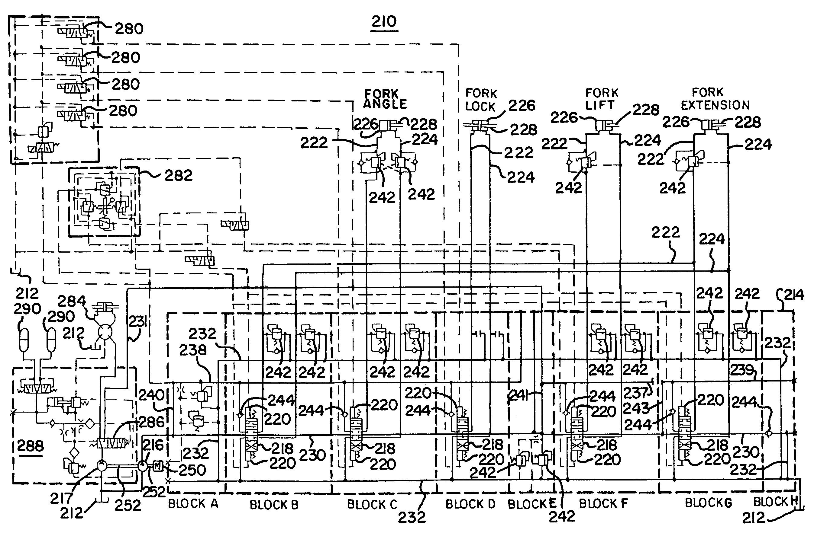
[0047]An embodiment of the smart flow sharing system 210 of the present invention is illustrated schematically in FIGS. 3 and 4 in a manner using schematic symbols that would be understood by persons skilled in the art. Once again, for ease of reference, the schematic of the smart flow sharing valve 214 is separated into blocks A-H.

[0048]Referring to FIG. 3, the smart flow sharing system 210 includes hydraulic fluid tanks 212, one or more open center hydraulic valve banks designed in the manner described and illustrated herein (“smart flow sharing valves”) 214, a first fixed displacement pump 216, a second fixed displacement pump 217, and a single motor 250 preferably running both the first and second fixed displacement pumps 216 and 217, with the motor 250 preferably driving first and second fixed displacement pumps 216 and 217 using a common single motor shaft 252. Each smart flow sharing valve 214 may include one or more spools 218, with each spool 218 activated by a pair of asso...


PUM


Abstract

A smart flow sharing system, useful in hydraulic systems having more than one hydraulically demanding equipment function wherein more than one of the hydraulically demanding functions are sometimes activated at the same time, has modified hydraulic passages and at least two fixed displacement pumps. The system automatically prioritizes hydraulic fluid flow so that when only one of two hydraulically demanding functions is activated by an operator, it receives the hydraulic fluid flow from both fixed displacement pumps, but when both hydraulically demanding functions are activated, one of the functions receives hydraulic fluid flow from the first fixed displacement pump, and the other function separately receives hydraulic fluid flow from the second fixed displacement pump. The smart flow sharing system accomplishes the foregoing without resorting to complex hydraulics or expensive additional components. An equipment operator advantageously achieves superior controllability and quicker movement of equipment functions using the invention.

Description

CROSS-REFERENCE TO RELATED APPLICATIONS[0001]This application claims priority from and is related to the following prior application: Smart Flow Sharing System, U.S. Provisional Application No. 61 / 015,463, filed Dec. 20, 2007. The prior application, including the entire written description and drawings figures, is hereby incorporated by reference into the present application.BACKGROUND OF THE INVENTION[0002]1. Field of the Invention[0003]The present invention relates to hydraulic valve systems used, for example, in off-road earth moving, construction, and forestry equipment, such as rough terrain forklifts (also known as telehandlers), earth movers, backhoes, articulated booms, and the like. Hydraulic valve systems are utilized, for example, to cause pistons to lower, lift, extend, retract, lock, unlock, or angle a fork in a telehandler. The present invention relates to an improved design for such hydraulic valve systems.[0004]2. Brief Description of the Related Art[0005]Prior art h...

Claims


Application Information

Patent Timeline
Patent Type & Authority Patents(United States)
IPC IPC(8): F16D31/02
CPCF15B11/17B66F9/22E02F9/2239E02F9/2292F15B2211/20538F15B2211/20576F15B2211/2654F15B2211/3116F15B2211/5059
Inventor HARSIA, JARMO, ANTERO
Owner PARKER INTANGIBLES LLC
Why Eureka
Try Eureka