System For a Portable Hands-Free Breast Pump and Method of Using the Same
a breast pump and hands-free technology, applied in the field of hands-free, visually friendly, portable breast pump systems, can solve the problems of electric pumps that may be self-cycling or require some manual user control, are cumbersome and difficult to use, and are typically uncomfortable, so as to facilitate the numerous benefits of breast-feeding, reduce the contamination of milk, and accurately emulate the suckling action of a baby.
- Summary
- Abstract
- Description
- Claims
- Application Information
AI Technical Summary
Benefits of technology
Problems solved by technology
Method used
Image
Examples
second embodiment
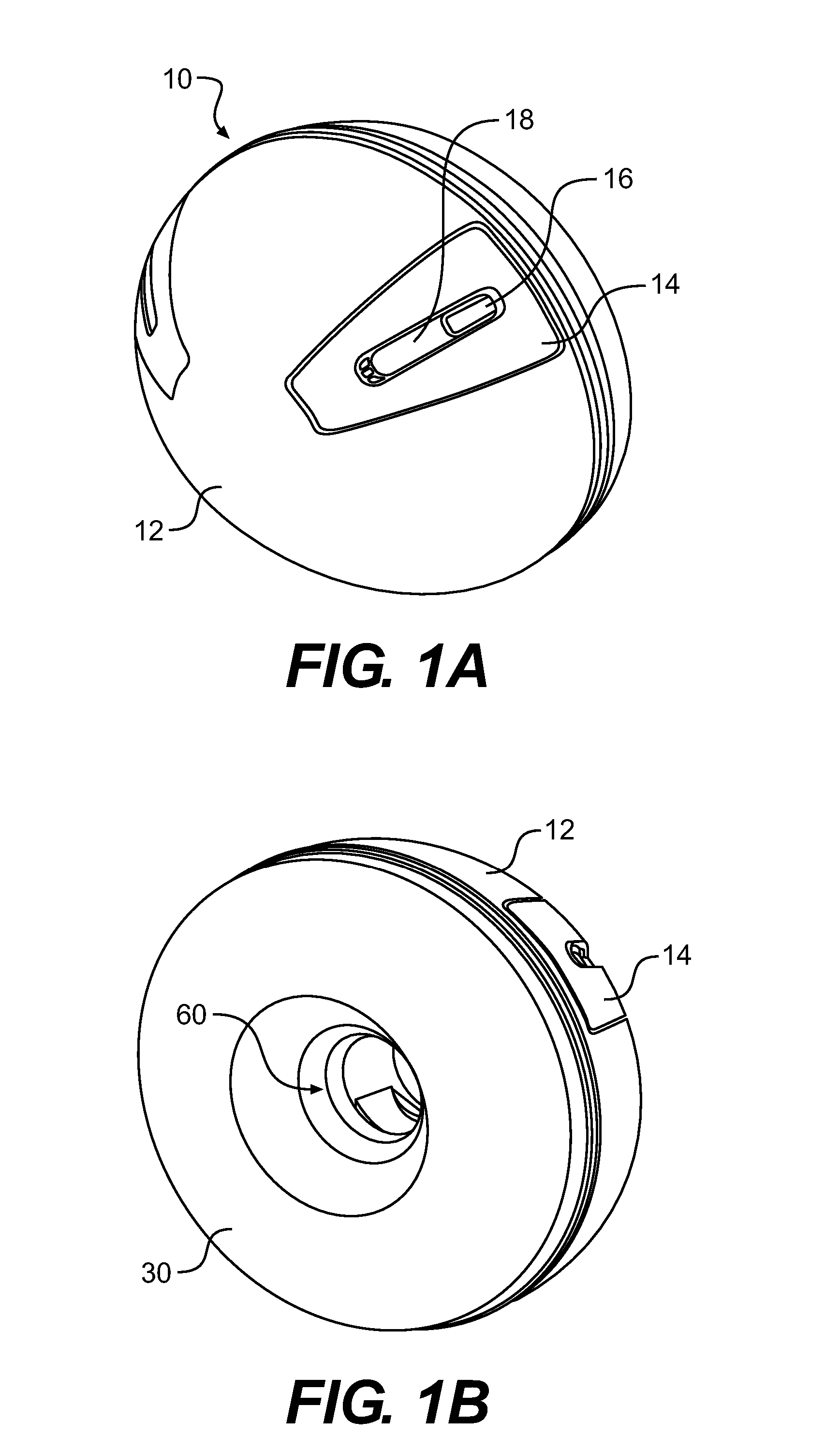
[0047] In a second embodiment shown in FIG. 3, the slide button 16 is configured to slide in a circumferential direction along the groove 18 so as to adjust the pumping action to continuously vary the vacuum level. A push button 20 is used to control the cycling rate by incrementally increasing the rate with each push of the button 20 up to the fastest cycling rate designed into the pump. A further push of the button 20 then rolls the increment back to the slowest cycling rate for a continuous loop operation. FIG. 4 depicts that the slide button 16 is connected to an electrical contacting base 21 with an arm 16a so as to slide the electrical contacting base 21 and vary the vacuum level.
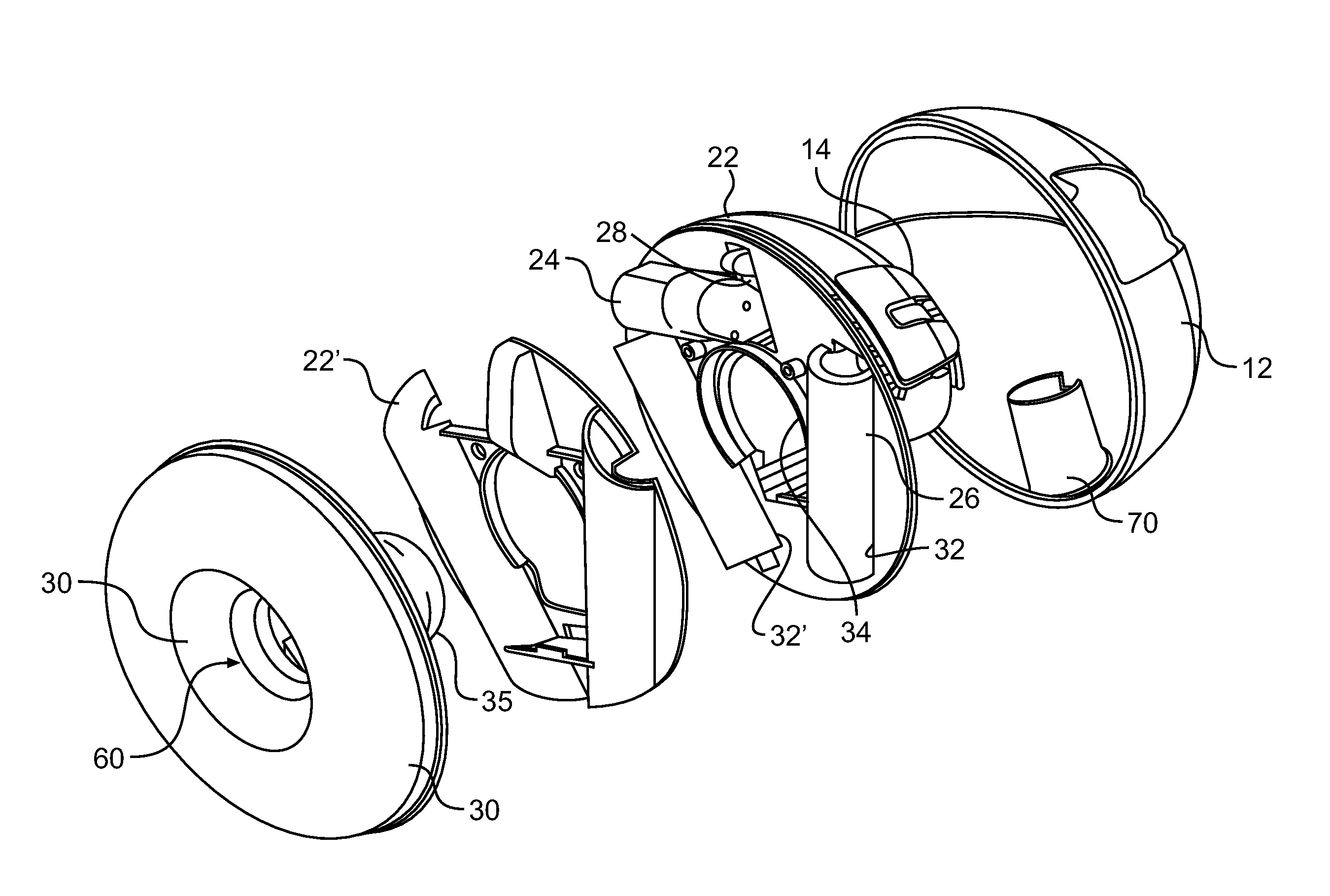
[0048] Referring to FIG. 5, each breast pump 10 includes a housing shell 12, a central deck 22 with a servomotor mechanism 24 integrated therewith, and a straw-hat shaped breast “flange”30 having a flange top 35. The servomotor mechanism 24 is a servomotor mechanism powered by at least one power sourc...
third embodiment
[0054] In the breast pump, power for the external servomotor mechanism 24 is located outside the housing. As shown in FIG. 8A, an adapter 46 is used to connect a positive contacting pin to the external power supply 26 via a wire 26a. FIG. 9 shows an inset view of how the adapter 46 is attached to the positive contacting pin 44. This embodiment has the advantage of a longer-lasting power supply that can be used, for example, in an institutional setting (i.e., a hospital) or even a home setting where a more limited range of mobility is acceptable or even desired.
[0055] Alternatively, as shown in FIG. 8B, the servomotor mechanism 24 may be replaced by a servomechanism 24′ that may be just a mechanical or pneumatic linkage 101 connected to the lever arm 21 for implementing the pumping action of the vacuum chamber 60. The linkage 101 is connected to a remote control 103 that acts as the user's control for pumping via a linkage element 103. For example, in a mechanical implementation, the...
first embodiment
[0063] In the rear-piston lever-arm system 100, as shown in the exploded view of FIG. 11A, the top of the piston cylinder 25 is shaped like a yo-yo or a doughnut without a hole. The lever arm 21 has a protrusion 21a on the top that contacts with the alignment dome 25b of the piston cylinder 25. The lever arm 21 is a projecting handle used to adjust or operate the piston cylinder 25. In particular, the-rear piston lever-arm system 100 mechanically communicates with the servomotor mechanism 24 so as to be activated by the mechanism and thereby pivotally move the lever arm 21 which then linearly moves the piston cylinder 25 along a line generally parallel with the centerline of the pump 10. Such a linear movement is depicted, wherein the start or “upstroke” position of the piston cylinder's linear movement is shown in FIG. 11B.
[0064]FIG. 11C shows the lever arm 21 pivoted forward thereby linearly pushing the piston cylinder toward the flange 30 in a “downstroke” motion. The lever arm 2...
PUM
 Abstract
Description
Claims
Application Information
 - R&D
- Intellectual Property
- Life Sciences
- Materials
- Tech Scout
- Unparalleled Data Quality
- Higher Quality Content
- 60% Fewer Hallucinations
Browse by: Latest US Patents, China's latest patents, Technical Efficacy Thesaurus, Application Domain, Technology Topic, Popular Technical Reports.
© 2025 PatSnap. All rights reserved.Legal|Privacy policy|Modern Slavery Act Transparency Statement|Sitemap|About US| Contact US: help@patsnap.com


