Eye implant and methods of positioning an artificial eye implant within the eye of a human or an animal
a technology of artificial eye and eye implant, which is applied in the field can solve the problems of affecting reducing the clinical value of artificial eye implants, so as to achieve the effect of minimal invasiveness
- Summary
- Abstract
- Description
- Claims
- Application Information
AI Technical Summary
Benefits of technology
Problems solved by technology
Method used
Image
Examples
first embodiment
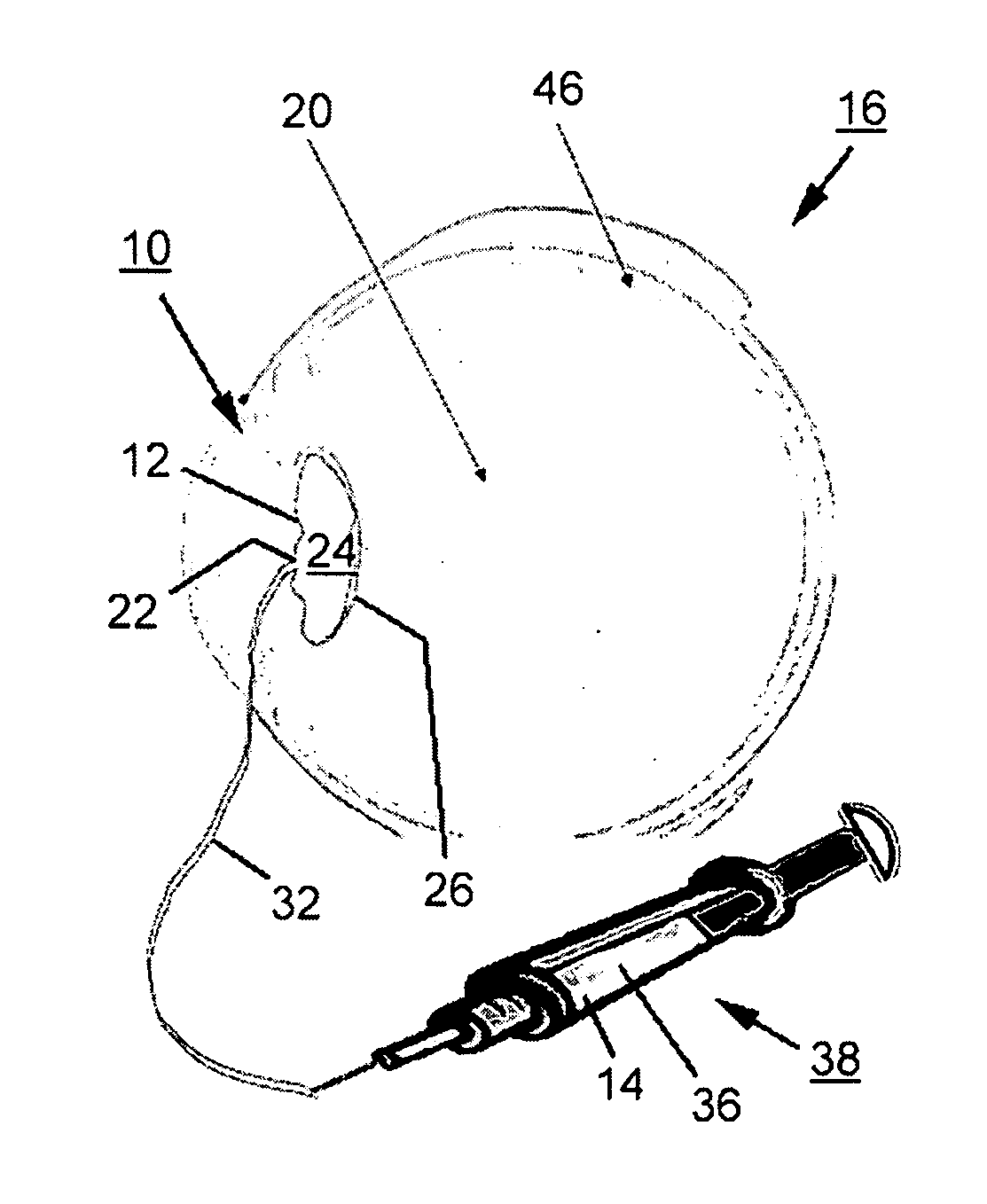
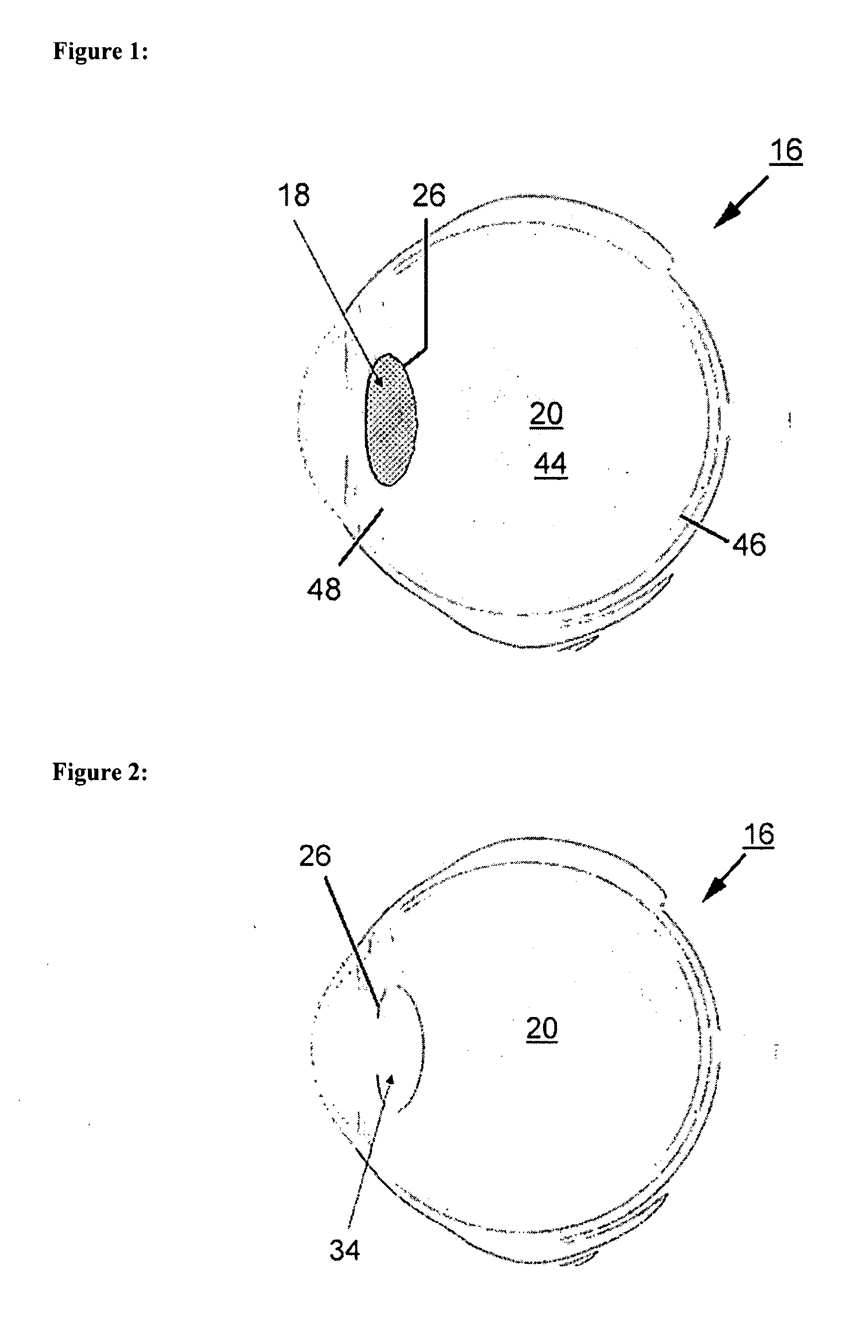
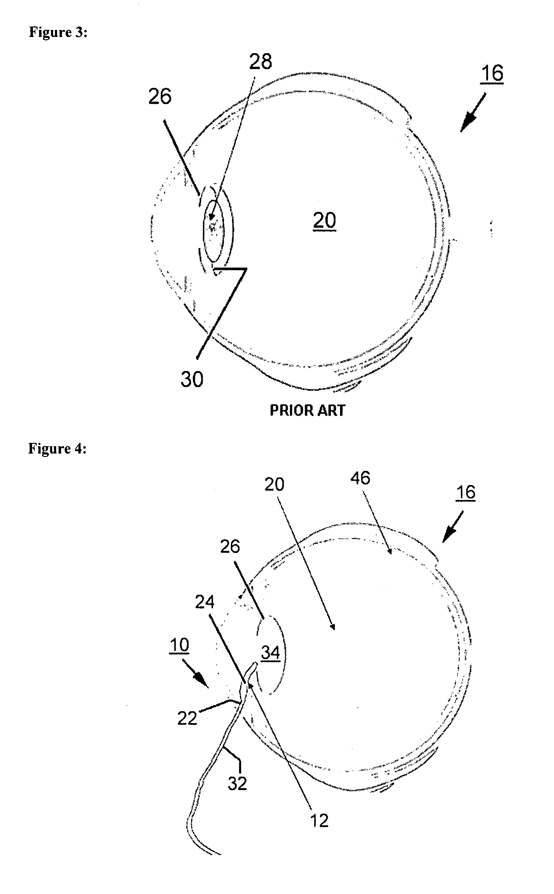
[0040]FIG. 4 shows a schematic representation of an artificial eye implant 10 according to the invention. Therein, the representation shows the eye implant 10 during introduction into the human eye 16. Therein, the introduction is effected through a small cut already used for removing the eye lens 18. One recognizes that the eye implant 10 shown in the illustrated embodiment serves as a substitute for the eye lens and includes a hollow body 12. Therein, the hollow body 12 is made of a biocompatible, flexible and extensible material and is able to be filled with a medium 14. As the materials for the artificial eye implant, especially biocompatible, flexible and extensible plastics, silicones and a plurality of other polymer compounds are considered, which have the requested properties. Silicone gum, acrylate, polyurethane, latex and polymethylmethacrylate (PMMA) are to be mentioned exemplarily.
[0041] Further, one recognizes that the eye implant 10 has a valve device 22 for filling th...
second embodiment
[0044]FIG. 8 shows a schematic representation of the eye implant 10 in a state filled with medium. One recognizes that instead of the tube connection 32, the medium 14 is now filled by means of a cannula 40 of a syringe-like filling device 38. Therein, the cannula 40 penetrates the valve device 22 of the hollow body 12 and thus places the medium 14 in the cavity 24 of the hollow body 12. After completely filling the cavity 24, the filling device 38 is retracted and the valve device 22 closes the hollow body 12. One recognizes that the eye implant 10 again has a curved front wall 50 and a curved back wall 52 facing the vitreous body 20 in the completely filled state.
third embodiment
[0045]FIG. 9 shows a schematic representation of an eye implant 10 during introduction into a posterior orbit 44 of the human eye 16. The vitreous body 20 has been removed from the posterior orbit 44. The eye implant 10 consisting of the hollow boy 12 with the cavity 24 is introduced into the posterior orbit 44 through a small cut, through which the vitreous body 20 has already been removed. Subsequently, the medium 14 is filled into the cavity 24 of the hollow body 12 through the valve device 22, the tube connection 32 detachably connected thereto, and the filling device 38 connected to the tube connection 32 (compare FIG. 10).
[0046] In state completely filled with the medium 14, illustrated in FIG. 11, the hollow body 12 approximately models the shape of the vitreous body 20 of the human or animal eye 16 and abuts the retina 46. After completely filling the hollow body 12, the tube connection 32 is detached from the eye implant 10 or the valve device 22 thereof, respectively.
PUM
 Abstract
Description
Claims
Application Information
 - R&D
- Intellectual Property
- Life Sciences
- Materials
- Tech Scout
- Unparalleled Data Quality
- Higher Quality Content
- 60% Fewer Hallucinations
Browse by: Latest US Patents, China's latest patents, Technical Efficacy Thesaurus, Application Domain, Technology Topic, Popular Technical Reports.
© 2025 PatSnap. All rights reserved.Legal|Privacy policy|Modern Slavery Act Transparency Statement|Sitemap|About US| Contact US: help@patsnap.com


