Method and device for producing a fluid-tight connection of layers of material and corresponding sealing

a technology of fluid tight connection and layer, applied in the direction of weaving, garments, applications, etc., can solve the problems of not being able to penetrate deep into the material, not being able to use as a reflector, and not being able to achieve the effect of high production accuracy

Inactive Publication Date: 2007-09-13
SEEGER THOMAS +1
View PDF0 Cites 2 Cited by
  • Summary
  • Abstract
  • Description
  • Claims
  • Application Information

AI Technical Summary

Benefits of technology

[0020] It is therefore an object of the present invention to provide a method and an apparatus for producing a liquid-tight connection between layers of material which ensures process reliability in the sense of high production accuracy and an associated reliable integrity of the seal of the connection. A further aim of the invention is to provide a sealing strip for sealing two layers of material connected to one another which is suitable for use in the method and permits great integrity of the seal of the layers of material connected to one another.
[0023] The laser beam makes it possible, by introducing a quite specific amount of energy, to set a very exact temperature at that position of the sealing strip or the layer of material at which the melting of the adhesive layer is intended to take place, so that virtually no differences in temperature occur any longer. This uniform temperature allows best possible melting characteristics of the adhesive layer to be set, which leads to optimum connection of the sealing strip to the layers of material or of the layers of material to one another.
[0024] It is consequently no longer necessary to set an excessive temperature in the region of the adhesive layer to achieve a secure adhesive bond. Rather, by dispensing with pressurized hot air and using the laser beam for melting the adhesive layer, very much lower temperatures are obtained in the working area, and as a result more pleasant working conditions if the layers of material and possibly the sealing strip are fed in manually. On account of these better working conditions, greater accuracy in manual working, and consequently better integrity of the seal of the connection, are of course also to be expected.
[0025] Since the light energy of a laser beam decreases only slightly with the distance from the laser source, such a laser source may be arranged at virtually any desired distance from the actual location to be heated or adhesively bonded, which advantageously leads to considerably increased flexibility in production.
[0026] The introduction of light energy into the adhesive layer for melting the same advantageously does not lead to air bubbles, as a result the integrity of the seal of the connection is obtained. At the same time a higher rate of advancement, better handling and consequently greater production reliability with reproducible results are achieved. The accuracy of the connection produced by the method according to the invention is ensured by the pinpoint accuracy of the melting of the adhesive layer with the laser beam.
[0027] A simple possibility for controlling the method according to the invention can be obtained if, in an advantageous development of the invention, the energy of the laser beam is controlled in dependence on the melting of the adhesive layer.

Problems solved by technology

However, the TiO.sub.2, proposed inter alia, can only be used as a reflector, not as an absorber.
A CO2 laser used in the case of this method is accompanied by the problem that it can only penetrate deep enough into the material in the case of certain materials, for example the materials PE and PP used there.
Furthermore, in the case of this solution it is attempted to change the depth of penetration of the laser beam with the aid of optical devices, but this is not possible According to the Lambert-Beer law.
However, no influence on the melting of the adhesive layer can be brought to bear in this way.
In this case, a pulsed laser is used for achieving very high amounts of energy and selective melting, but is very difficult to control.
The method used there is transmission laser welding, in which both components to be connected are melted, which, however, when using textiles, would lead to the same being melted and consequently destroyed.
A further problem is the great restriction on the selection of colors of the plastics, to allow the method described to be carried out.
However, this method cannot ensure water tightness of the connection.
A special laser is used, with for the most part superficial absorption, as a result of which uniform melting of the adhesive layer cannot be achieved.
However, the binding strip used there is of a relatively complicated construction and therefore both complex to produce and difficult to handle.
However, this method has a great number of disadvantages, which on the one hand arise due to the fact that the temperature produced by means of the hot air of several hundred .degree. C. in the region of the adhesive layer cannot be accurately measured, and therefore cannot always be correctly set, so that it is very difficult to make statements about the quality of the sealing connection.
This usually has the effect that an excessive temperature is produced, which results in further disadvantages, such as the burning of oil, necessary for generating pressure, contained in the air and of other contaminants, and the resultant development of smoke, which brings with it adverse effects on the health of the operators, increased temperatures at the workplace and increased energy consumption.

Method used


Image

  • Method and device for producing a fluid-tight connection of layers of material and corresponding sealing
  • Method and device for producing a fluid-tight connection of layers of material and corresponding sealing
  • Method and device for producing a fluid-tight connection of layers of material and corresponding sealing

Examples


Embodiment Construction

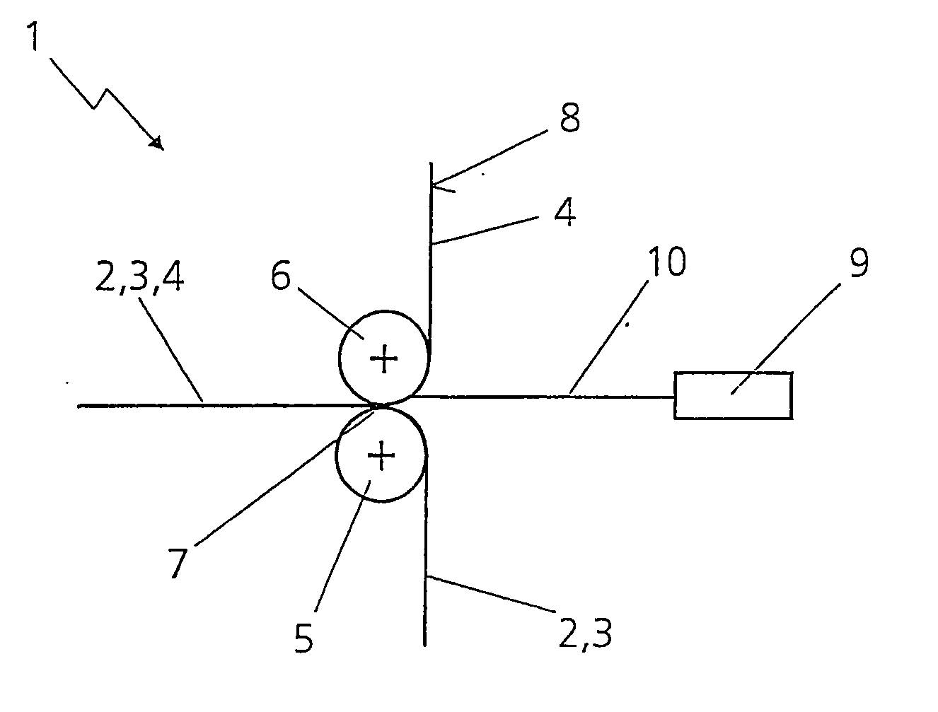
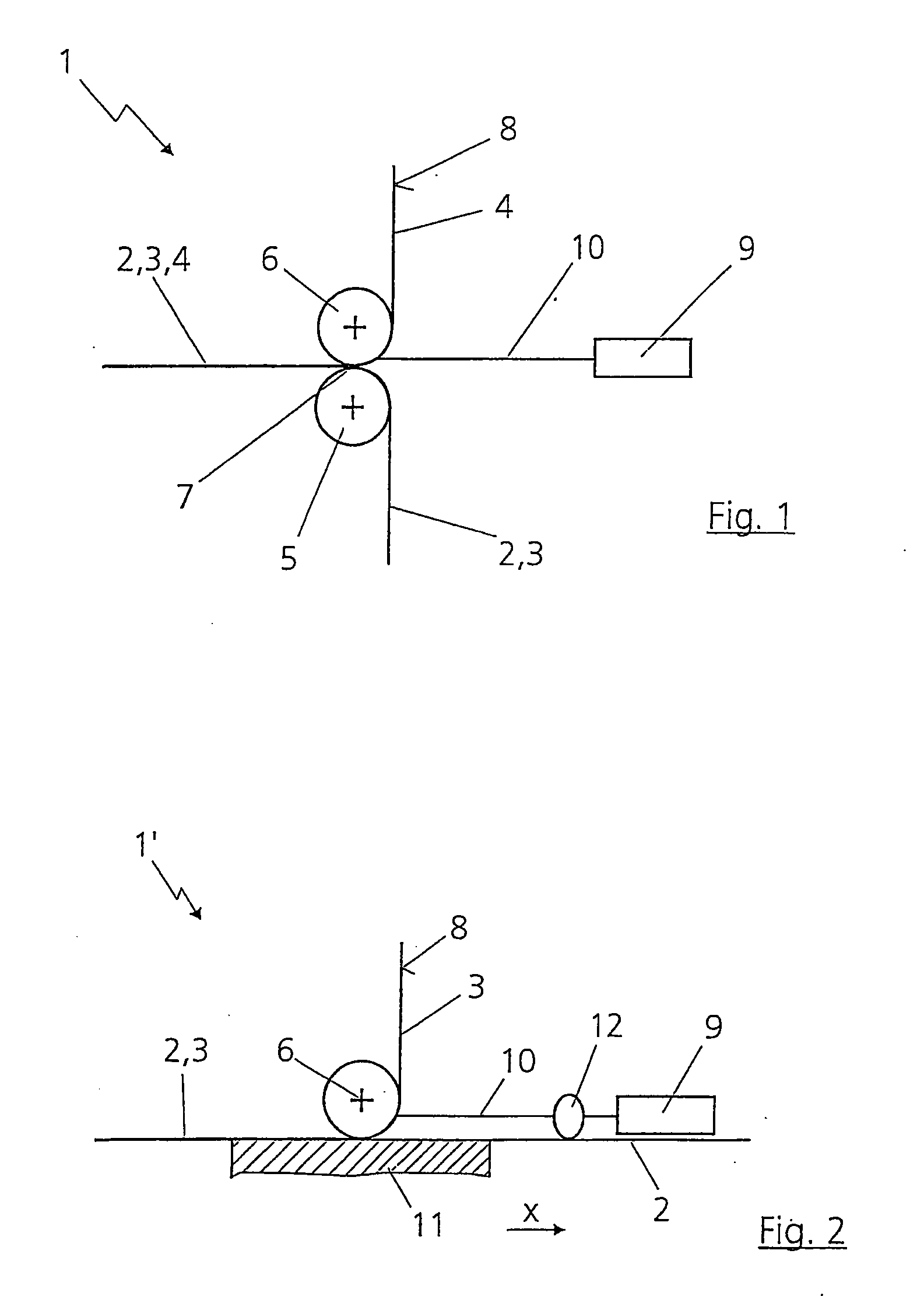
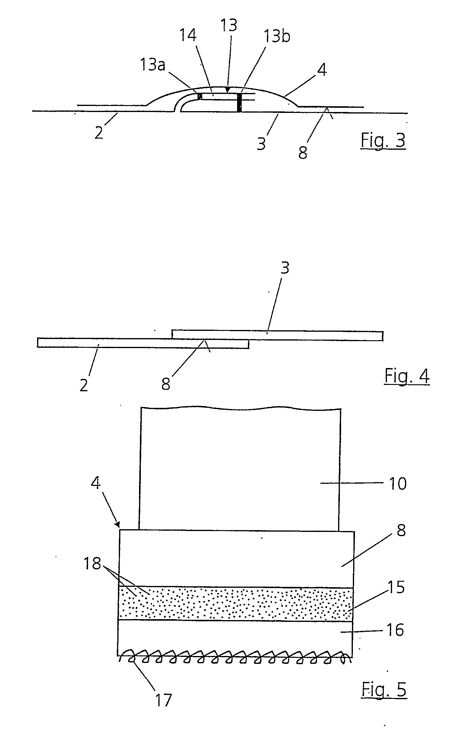
[0038]FIG. 1 shows an apparatus 1 for sealing a seam (which cannot be seen here), which connects two layers of material 2 and 3, preferably textile fabrics, to one another. Provided for the sealing is a sealing strip 4, the structure of which is described in more detail later with reference to FIG. 5. The connection of the layers of material 2 and 3 produced with the sealing strip 4 by means of the apparatus 1 and the method described below is represented in more detail in FIG. 3.

[0039] The apparatus 1 has two rollers 5 and 6, which are both set in rotation by means of respective drive devices (not represented), for example an electric motor. The first roller 5, rotating counterclockwise, is provided for transporting the sewn-together layers of material 2 and 3, whereas the second roller 6, rotating clockwise, transports the sealing strip 4. Between the two rollers 5 and 6 there is a roller nip 7, in which the sealing strip 4 is pressed with the layers of material 2 and 3 in such a...


PUM

PropertyMeasurementUnit
Transparencyaaaaaaaaaa
Energyaaaaaaaaaa
Lightaaaaaaaaaa

Abstract

In the case of a method for producing a liquid-tight connection between layers of material, in particular textile fabrics, an adhesive layer of an additional sealing strip that seals the layers of material is melted by means of a laser bean. After that, the sealing strip is connected to the layers of material. A relative movement takes place between the laser beam and the sealing strip.

Description

CROSS REFERENCE TO RELATED APPLICATION [0001] This application is a divisional application of patent application Ser. No. 10 / 855,019, filed on May 27, 2004, which is a Continuation-in-part of PCT Application No. PCT / EP02 / 13272, filed on Nov. 26, 2002, which claims priority of German patent application No. 101 58 016.0, filed on Nov. 27, 2001. All parent applications are herein incorporated by reference in their entirety.FIELD OF THE INVENTION [0002] The invention relates to a method for producing a liquid-tight connection between layers of material, in particular textile fabrics. Furthermore, the invention relates to a sealing strip for sealing two layers of material connected to one another. BACKGROUND OF THE INVENTION [0003] In the case of a method described in WO 01 / 81082A1, two layers of material are connected to one another by heating of the same, with thermal radiation or hot air being used. Among possible techniques is that of using a laser for evaporating solvent or for remo...

Claims


Application Information

Patent Timeline
IPC IPC(8): B32B5/02A41D27/24B29C65/16B29C65/50B29C65/62
CPCA41D27/24Y10T428/2848B29C65/1632B29C65/5042B29C65/62B29C66/112B29C66/1122B29C66/135B29C66/43B29C66/90B29K2313/00B29K2995/0069A41D27/245Y10T428/28B29C65/5014B29C65/5021B29C65/1658B29C65/168B29C65/1683B29C66/83413B29C66/91216B29C66/91221B29C66/961B29C66/91411B29C66/9161B29C65/4815B29C65/00B29C66/73921B29C66/73941Y10T442/2738
Inventor SEEGER, THOMASHAENSCH, DIRK
Owner SEEGER THOMAS
Why Eureka
Try Eureka