Optical disc reproducing apparatus

a technology of optical discs and reproducing apparatuses, applied in the field of optical disc reproducing apparatuses, can solve the problems of difficult detection and correction, difficult to execute detection and correction, and often faced problems of conventional optical discs, so as to improve the accuracy of detecting data, accurately estimating the signal model, and accurate compensating

Inactive Publication Date: 2007-09-06
SAMSUNG ELECTRONICS CO LTD
View PDF4 Cites 4 Cited by
  • Summary
  • Abstract
  • Description
  • Claims
  • Application Information

AI Technical Summary

Benefits of technology

[0016]The present invention also provides an optical disc reproducing apparatus, which is capable of detecting data more accurately by amplifying a high frequency signal component regardless of an occurrence or an increase of both a noise of a signal and a signal interference, and of measuring a signal quality, and of estimating a frequency.
[0017]The present invention also provides an optical disc reproducing apparatus which is capable of adjusting target channel features of both an equalizer and a Viterbi decoder by accurately estimating signal models of both the equalizer and the Viterbi decoder according to each feature of a record reproducing channel.
[0018]The present invention also provides an optical disc reproducing apparatus which is capable of accurately compensating for a minute asymmetry feature of the signal in the record reproducing channel.
[0019]The present invention also provides an optical disc reproducing apparatus accurately which is capable of estimating a frequency of a synchronous pattern having a symmetric feature.
[0020]The present invention also provides an optical disc reproducing apparatus which is capable of supporting various signal patterns including cases in which a minimum T is 2 or 3, and accurately detecting a signal by corresponding to a high-speed signal.

Problems solved by technology

Such kinds of conventional optical discs may be often confronted with problems as follows.
Furthermore, this asymmetric phenomenon may give rise to other unfavorable phenomena such as a jitter, a non-linear bit offset, a direct current (DC) offset, and an inter-symbol interference (ISI) between symbols of reproduced data.
Such phenomena often make it difficult to execute a detection and a correction of frequency errors and phase errors, thus causing the distortion of reproduced signals.
However, the related art DSV algorithm does not always execute an exact correction of the asymmetric errors under various code environments such as RLL(1,10) and RLL(2,10).
For example, the related art DSV algorithm may often fail to exactly detect asymmetric errors in the case of 4T sampling signals reproduced in the variable frequency oscillator (VFO) sector of the optical disc.
Furthermore, the related art optical disc reproducing apparatus does not support an integrated solution for both RLL(1,10) and RLL(2,10) codes.
This configuration of the detectors may, however, be inefficient in circuit area use and power consumption.
Also, according to the related art optical disc reproducing apparatus, as a signal of a high frequency is amplified, a signal interference phenomenon occurs.
Also, accurately measuring a signal quality and estimating a frequency may not be easily executed.
Also, according to the related art optical disc reproducing apparatus, when a feature of the signal is deteriorated, accurate signal models of both an equalizer and a Viterbi decoder may not be set up.
Accordingly, a signal detecting operation may not be accurately executed.
Also, according to the related art optical disc reproducing apparatus, a related art DSV algorithm does not detect and compensate a minute DC offset information in a record reproducing channel.
Also, a phase locked loop (PPL) operation may be unstably executed.
Also, according to the related art optical disc reproducing apparatus, when the feature of the signal is deteriorated, a frequency estimating operation may not be executed.

Method used


Image

  • Optical disc reproducing apparatus
  • Optical disc reproducing apparatus
  • Optical disc reproducing apparatus

Examples


Embodiment Construction

[0046]Reference will now be made in detail to certain exemplary embodiments of the present invention, examples of which are illustrated in the accompanying drawings, wherein like reference numerals refer to the like elements throughout. The exemplary embodiments are described below in order to explain the present invention by referring to the figures.

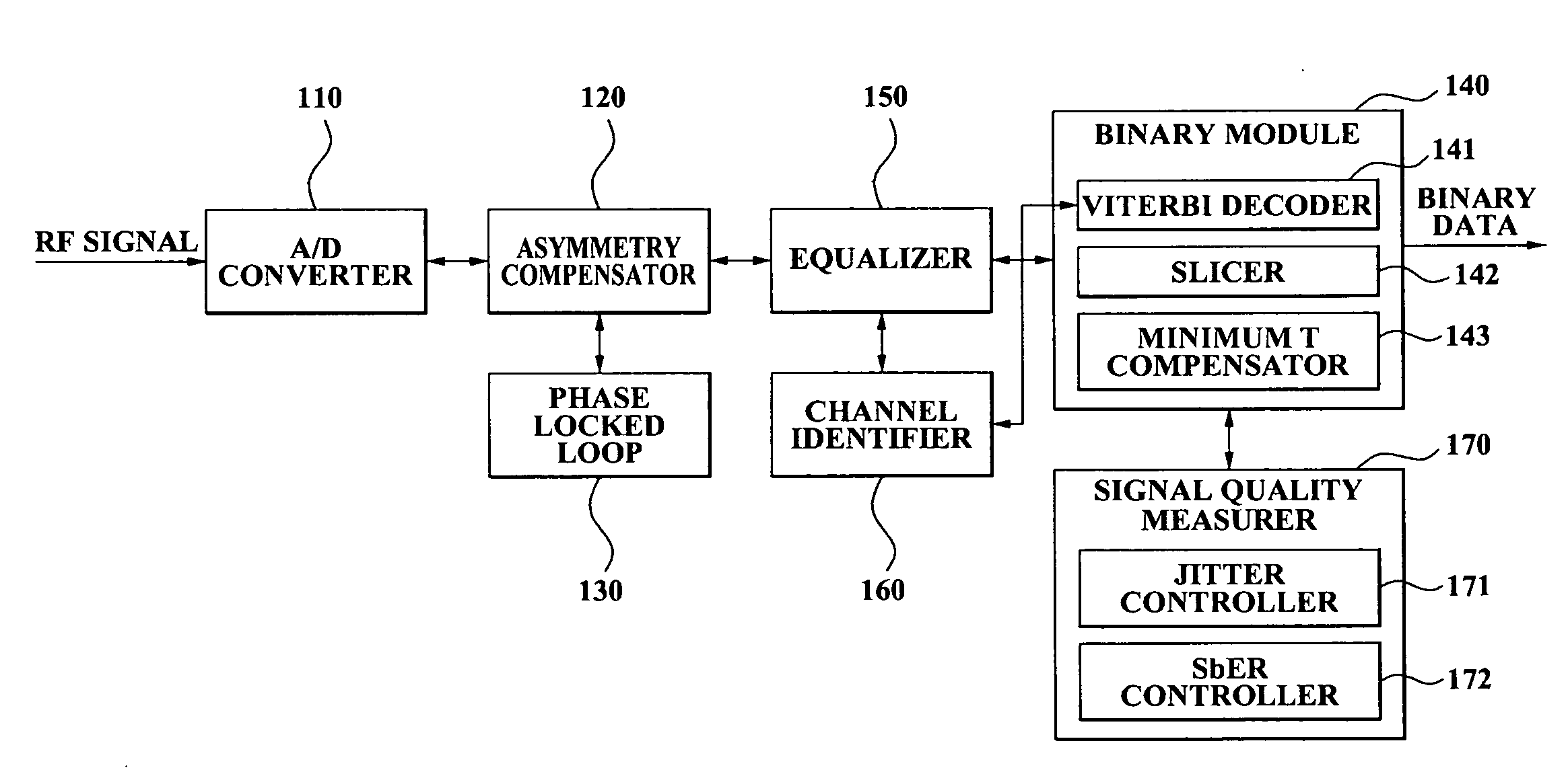
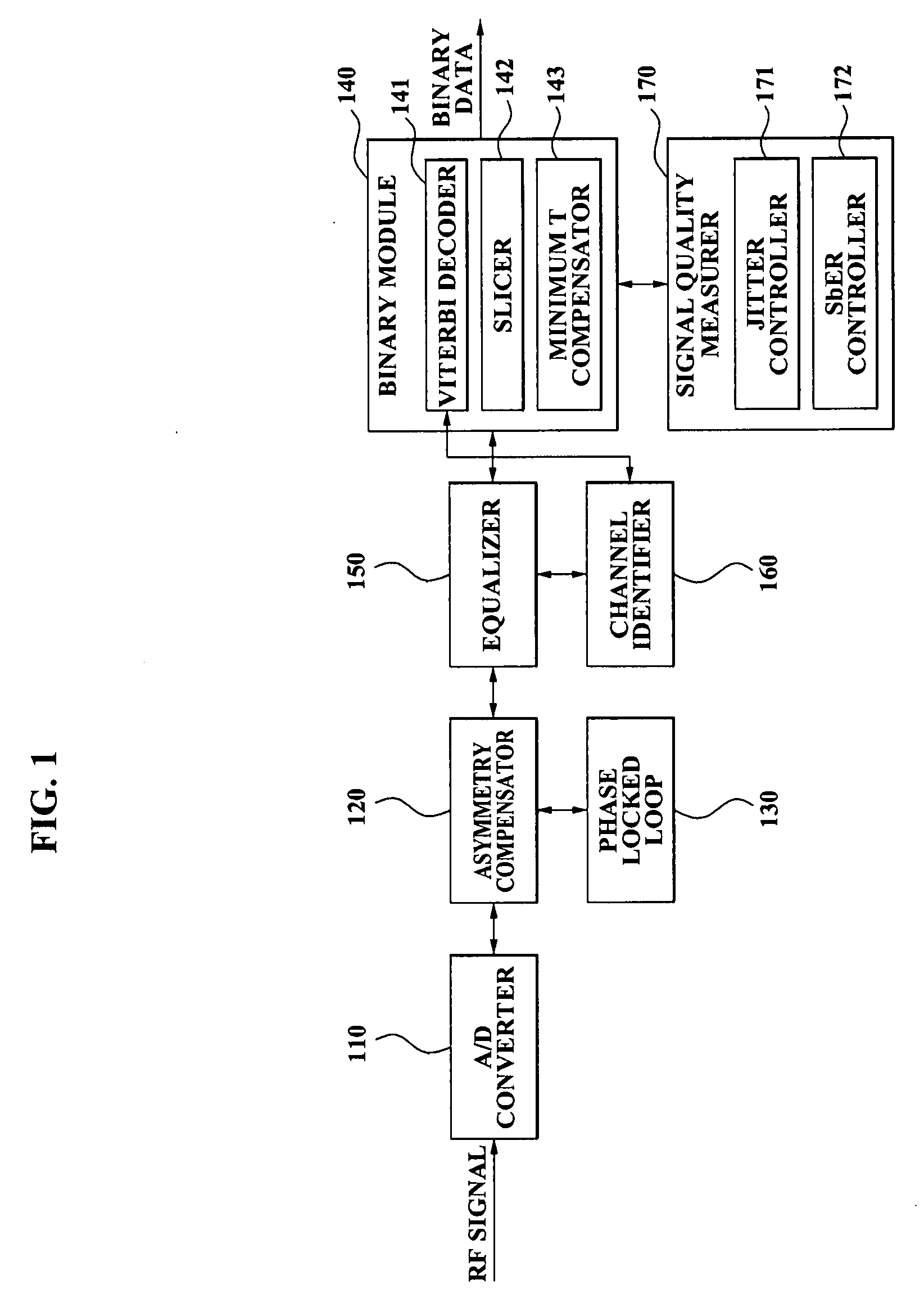
[0047]FIG. 1 is a diagram illustrating an optical disc reproducing apparatus according to an exemplary embodiment of the present invention.

[0048]The optical disc reproducing apparatus according to an exemplary embodiment of the present invention includes an analog-to-digital (A / D) converter 110, an asymmetry compensator 120, a phase locked loop (PLL) 130, a binary module 140, an equalizer 150, a channel identifier 160, and a signal quality measurer 170. The binary module 140 includes a Viterbi decoder 141, a slicer 142, and a minimum T compensator 143. The signal quality measurer 170 includes a jitter controller 171 and a simulated bit ...


PUM

PropertyMeasurementUnit
frequencyaaaaaaaaaa
sizeaaaaaaaaaa
weightaaaaaaaaaa

Abstract

An optical disc reproducing apparatus includes an analog-to-digital (A/D) converter which converts an analog signal obtained from an optical disc to a digital signal; an asymmetry compensator which detects and corrects an offset of the digital signal; a phase locked loop (PLL) which estimates a clock of the digital signal and compensates for a frequency error; a binary module which converts the digital signal to binary data; an equalizer which equalizes a particular frequency of the digital signal; and a channel identifier which detects a reference level of the binary module, based on an input signal of the equalizer.

Description

CROSS-REFERENCE TO RELATED APPLICATION[0001]This application claims priority from Korean Patent Application No. 10-2006-0020667, filed on Mar. 3, 2006, in the Korean Intellectual Property Office, the entire disclosure of which is incorporated herein by reference.BACKGROUND OF THE INVENTION[0002]1. Field of the Invention[0003]Apparatuses consistent with the present invention relate to an optical disc reproducing apparatus, and more particularly, to an optical disc reproducing apparatus supporting various Run Length Limited (RLL) codes such as RLL(2,1), RLL(1,7) and RLL(1,10), wherein the optical disc reproducing apparatus compensates for minute asymmetrical features of a partial response (PR)(abcde) channel, and a PR signal and supports an accurate detection of data, a jitter measurement and a signal synchronization, and a 16 level 5-tap Viterbi decoder.[0004]2. Description of Related Art[0005]With the multimedia era beginning, needs for storing and transmitting a large quantity of d...

Claims


Application Information

Patent Timeline
Patent Type & Authority Applications(United States)
IPC IPC(8): G11B20/10
CPCG11B20/10009G11B20/10037G11B2220/2562G11B20/10333G11B20/10425G11B20/10046G11B7/005G11B20/10
Inventor CHO, EING SEOBRYU, EUN JINLEE, JUNG HYUNKONG, JUN JIN
Owner SAMSUNG ELECTRONICS CO LTD
Why Eureka
Try Eureka