Systems and methods for switching between autonomous and manual operation of a vehicle

Active Publication Date: 2007-08-23
DEERE & CO +1
View PDF61 Cites 236 Cited by
  • Summary
  • Abstract
  • Description
  • Claims
  • Application Information

AI Technical Summary

Benefits of technology

[0010] Embodiments of this invention provide a vehicle, structures, systems, and methods, that are equally capable in autonomous and manual modes: (i) by incorporating enhanced safety in all such modes; (ii) by being readily restorable to fully mechanical manual operation and switchable to fully autonomous operation; (iii) by efficiently overlapping and combining components of autonomous control systems, manual mechanical control systems, and safety systems; or (iv) by having a human interface that simplifies processes of switching between autonomous and manual operations of a vehicle and enhances the operability and safety of vehicle use in either mode.
[0013] Another embodiment of the present invention is a vehicle that includes a safety stop system that enhances safety in all modes and efficiently overlaps and combines components of autonomous control systems, manual mechanical control systems, and safety systems. The safety stop system removes power from all moving parts and from all parts that cause the vehicle to move. The e-Stop system is a subsystem of the safety stop system. It includes normally disengaged electrical clutches associated with each system that causes the vehicle to move and powers down all of the clutches in an E-Stop. In one embodiment, even though the E-Stop removes power from the clutches, it leaves power in the autonomous control system. After an E-Stop the vehicle is immediately available to be driven by the operator via the mechanical vehicle operation systems. Because supervisory and other autonomous control systems remain powered, however, autonomous functions such as sensing, communications, recording, monitoring, etc., are allowed to continue. E-Stop can be triggered by E-Stop switches within the vehicle, or by operator control members for the mechanical vehicle operation systems, such as the brake pedal.
[0015] In another embodiment of the present invention, a vehicle includes an autonomous mode starting system and method that provide features to enhance safety. The vehicle includes a parking control element that is set in a predetermined setting when the vehicle is parked. This predetermined setting should be commonly perceived as signifying disabling movement, e.g., should be part of the ordinary rules of the road and / or ordinary driver training. For example, there may be a parking brake lever that is set in the “set position,” so that the parking brake lever extends upwards and is visible from outside the vehicle. The vehicle's control system interprets the predetermined setting as permitting autonomous mode. There may be a disengaging mechanism that is responsive to signals sent by the control system. The disengaging mechanism disengages the mechanism preventing autonomous movement, yet leaves the control element in the predetermined setting that signifies disabled movement. So for example, the disengaging mechanism would release the brakes so that the vehicle can move, but would not release the parking brake lever, which would remain in the “set position.” Optionally, the disengaging mechanism is electrical and would be deactivated under E-Stop or power loss conditions. It is optional, but advantageous, to leave the parking control electrically disengaged but mechanically “charged,” or mechanically biased. In this manner, the parking control can be reengaged under electrical control or can fail-safe to a braking condition when electrical power is lost.
[0016] In another embodiment of the invention, a robotics safety system is provided for enhancing safety when the vehicle is in autonomous mode and a passenger desires to use manual mode. In autonomous mode electrical clutches are engaged to prohibit operation in manual mode. The vehicle has a set of manual operation members, such as levers and steering wheels, that are accessible to the passengers. When a passenger moves any of the manual operation members the electrical clutches disengage to permit operation in manual mode, and prohibit operation in autonomous mode. In another embodiment, the robotics safety system may include a rocker switch or other switch with autonomous and manual settings that passengers may use to switch between modes. Before switching between modes the robotics safety system first enters a safety mode. Preferably, this safety mode includes bringing the vehicle to a controlled stop with the engine running. Following the safety mode, the robotics control system permits the passenger to control the vehicle by the same manual operation modes that were used to initiate the safety mode.

Problems solved by technology

For example, a steering wheel on such a vehicle might still be turned by a human, but would encounter unnatural and sometimes dangerous resistance from a still-attached robotic actuator.
While it is known that some of the vehicles were driven to the site on each day of competition, none are known to have been equally capable as autonomous vehicles and as manually driven vehicles.
None were safe both in an autonomous role and in a manual role—the course was cleared of all spectators, and passengers were not allowed during autonomous operation.
These drive-by-wire systems do not have a connection to an operable mechanical control for ordinary driving (such as a lever, pedal, or steering wheel directly operated by cable tension or hydraulic lines).
Retrofitted vehicles that use the intervening robotic software, electronics, and actuators in place of a disabled mechanical connection cannot be considered equally as capable as a conventional vehicle.
They may be fully or partially disabled upon failure of robotic control systems.
It may be difficult for passengers in such a vehicle to recover from accidents, e.g., removing the vehicle from a ditch if it becomes stuck.
In extreme scenarios, such as military operations, a converted “one-way” vehicle lacks flexibility.
Trivial software problems may strand a drive-by-wire vehicle, at least because there are no mechanical connections for a driver to resume use of the basic operational systems of the vehicle.
Known converted-to-robotics vehicles inherit this problem, and cannot be readily changed into fully manual vehicles at whim.
There are other problems—for example, converted vehicles do not drive or perform in the manner of an unmodified vehicle from an operator's perspective.
Simple activities, such as parking the vehicle in a garage or transport, may be more difficult than doing so in an ordinary manual vehicle, requiring complex programming or use of tele-operation.
To the extent that the prior art has contemplated some of the problems and opportunities associated with vehicles useful in both autonomous modes and manual modes, ergonomic and intuitive operation is usually not the primary problem addressed.
For example, although it may be contemplated that one manual operation or another may be associated with switching between autonomous and manual modes, specific, ergonomically determined mode switching methods are not well defined.
In this manner, the parking control can be reengaged under electrical control or can fail-safe to a braking condition when electrical power is lost.

Method used


Image

  • Systems and methods for switching between autonomous and manual operation of a vehicle
  • Systems and methods for switching between autonomous and manual operation of a vehicle
  • Systems and methods for switching between autonomous and manual operation of a vehicle

Examples


Embodiment Construction

[0035] Embodiments of this invention provide systems and methods for switching between autonomous and manual operations of a vehicle. More specifically, embodiments of this invention provide a vehicle, structures, systems, and methods, that are equally capable and in autonomous and manual modes: (i) by providing enhanced safety in all such modes; (ii) by being readily restorable to fully mechanical manual operation and switchable to fully autonomous operation; (iii) by efficiently overlapping and combining components of autonomous control systems, manual mechanical control systems, and safety systems; or (iv) by having a human interface that simplifies processes of switching between autonomous and manual operations of a vehicle and enhances the operability and safety of vehicle use in either mode.

Illustrative Vehicle

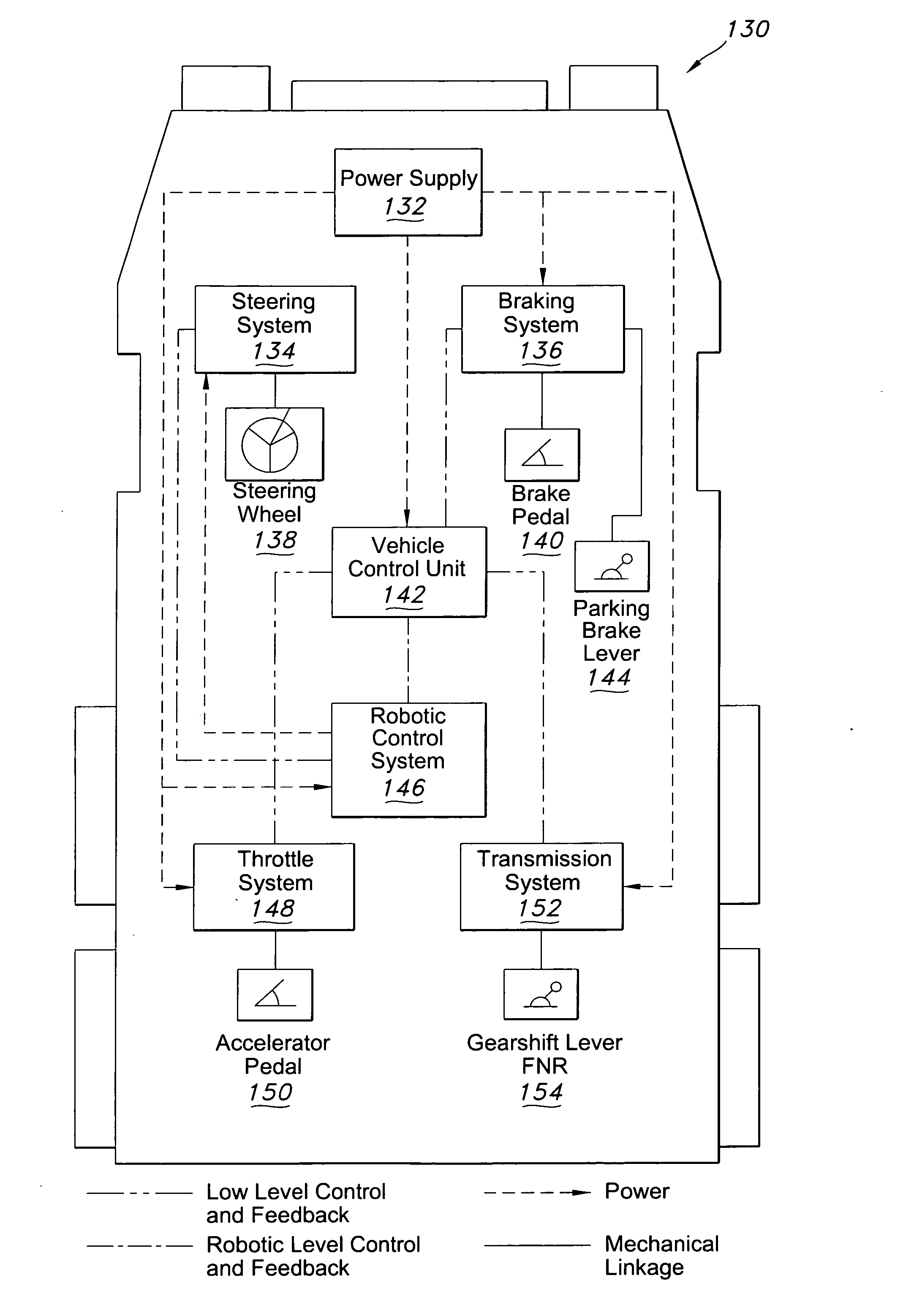
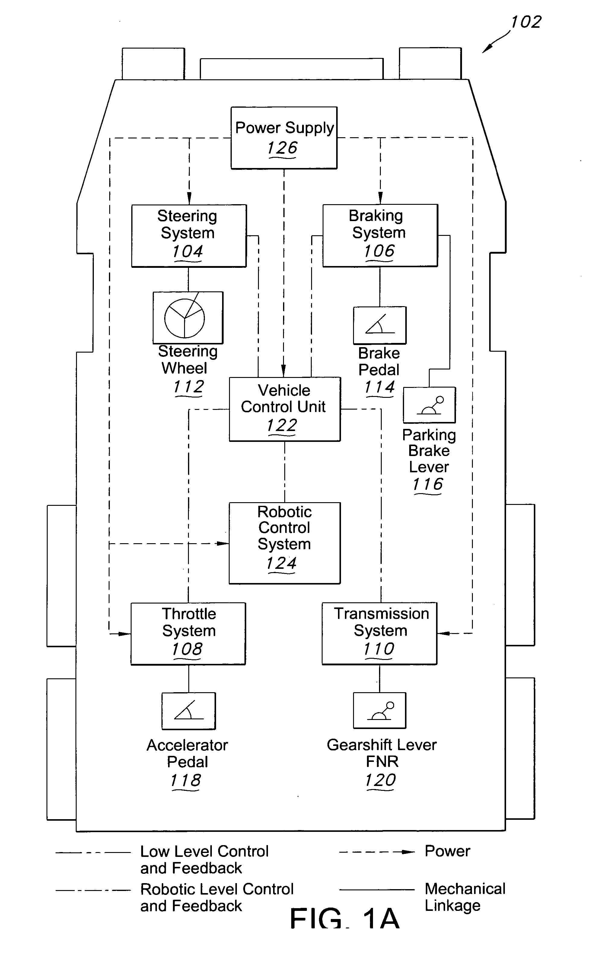
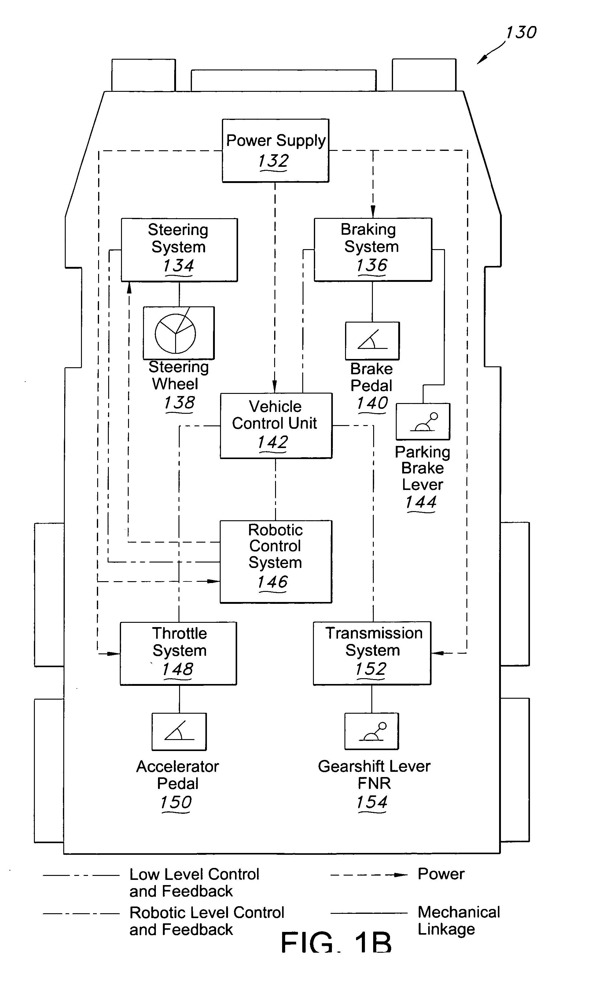
[0036] Embodiments of the present invention may be used in a variety of vehicles, such as automobiles, trucks, and utility vehicles. FIG. 1 is a block diagram of an il...


PUM


Abstract

Systems and methods for switching between autonomous and manual operation of a vehicle are described. In one embodiment, there is a mechanical control system that receives manual inputs from a mechanical operation member to operate the vehicle in manual mode. There is further an actuator that receives autonomous control signals generated by a controller. When the actuator is engaged, it operates the vehicle in an autonomous mode, and when disengaged, it operates the vehicle in manual mode. In another embodiment, there is an E-Stop system to disengage systems that cause the vehicle to move, such as the engine, while still leaving power in the systems that do not cause the vehicle to move. There is a method for autonomous mode starting of a vehicle, comprising receiving a signal indicating autonomous mode, determining that a parking brake lever is set and the brakes are engaged, disengaging the brakes while maintaining the lever in the set position, and engaging in autonomous mode. There is a safety system with a mechanical bias to suppress moveable systems of the vehicle, comprising a clutch that releases the mechanical bias to permit movement of the moveable system when the clutch is engaged. In another embodiment a system comprises a mechanical linkage with a restoration member that permits control of an operation system of the vehicle by a remote operation member when the restoration member is engaged. There is also an actuator that prohibits control of the operation system by the remote operation member when the actuator is engaged.

Description

CROSS REFERENCE TO RELATED APPLICATIONS [0001] This application claims priority to U.S. Provisional Patent Application No. 60 / 729,445, filed Oct. 21, 2005, U.S. Provisional Patent Application No. 60 / 729,388, filed Oct. 21, 2005, U.S. Provisional Patent Application No. 60 / 780,389, filed Mar. 8, 2006, and U.S. Provisional Patent Application No. 60 / 838,704, filed Aug. 18, 2006, each of which is incorporated herein by reference in its entirety. [0002] This application is related to U.S. Patent Applications entitled “Robotic Control Module”[Attorney Docket No. 56516 / 335073]; “Systems and Methods for Obstacle Avoidance” [Attorney Docket No. 56516 / 335072]; and “Networked Multi-Role Robotic Vehicle” [Attorney Docket No. 56516 / 335069], each of which is filed herewith and incorporated herein by reference in its entirety.FIELD OF THE INVENTION [0003] This invention relates generally to systems and methods for vehicle operation. More particularly, embodiments of this invention relate to systems...

Claims


Application Information

Patent Timeline
IPC IPC(8): G05D1/00
CPCG05D1/0246Y10S901/47G05D1/0259G05D1/027G05D1/0272G05D1/0274G05D1/0278G05D1/028G05D2201/0201G05D2201/0202G05D2201/0209G05D2201/0213G05D2201/0216B60T7/22B60W30/09B60W30/095B62D1/286G05D1/0061G05D1/024G05B19/414G05D1/021Y10S901/01G05D1/0251G05D1/0088G05D1/02G05B19/042B60W60/0051B60W60/0053H04L67/12
Inventor NORRIS, WILLIAM ROBERTALLARD, JAMESFILIPPOV, MIKHAIL O.HAUN, ROBERT DALETURNER, CHRISTOPHER DAVID GLENNGILBERTSON, SETHNORBY, ANDREW JULIAN
Owner DEERE & CO
Why Eureka
Try Eureka