Prosthetic joint

a prosthetic joint and joint technology, applied in the field of orthopaedic implants, can solve the problems of limited life span of prosthetic joints, joint loosening, and joint failure, and achieve the effects of reducing the life of prosthetic joints

Inactive Publication Date: 2007-08-23
WORT CHRISTOPHER JOHN HOWARD
View PDF7 Cites 9 Cited by
  • Summary
  • Abstract
  • Description
  • Claims
  • Application Information

AI Technical Summary

Benefits of technology

[0010] a metal insert secured in the recess, the metal insert having a socket sized and shaped to receive an end of a stem or joint hinge.

Problems solved by technology

Prosthetic joints suffer from limited life spans, typically of the order of 15 years or less, whilst the market requirement for prosthetic joints is that they are viable for much greater periods.
Such ball and socket arrangements, however, invariably result in frictional wear of the spherical ball and the UHMWPE lining, releasing very fine particles.
As a consequence, osteolysis takes place as agents, which are released as a result of the histiocytic reactions, attack the neighbouring bone, causing joint loosening and ultimately joint failure.
However, the problems of wear debris being formed as a result of friction still occur, with the same consequences as previously mentioned.
Whilst this addresses the problems associated with wear debris, potential for prosthetic joint failure due to other causes still exists.
A problem with ceramics is that although mechanically strong under compression, they generally have a low fracture strength under tension.
Accordingly, the stress concentrations at the corners of the tapered stem in the ceramic ball are prone to cause fractures in the ceramic and thus premature joint failure.

Method used


Image

  • Prosthetic joint
  • Prosthetic joint

Examples


Embodiment Construction

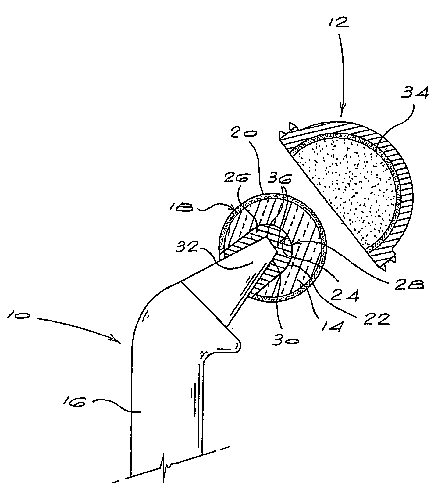
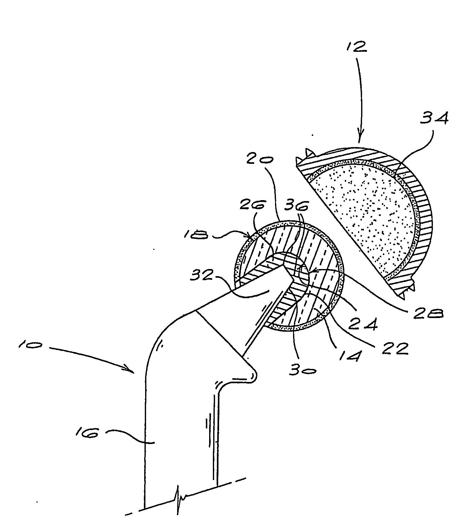
[0027] Referring to the accompanying drawing, a prosthetic joint ball component 10 of the invention is receivable in a prosthetic joint socket component 12 to form a prosthetic joint. The ball component 10 comprises a generally spherical ball 14 mounted on a stem 16. The outer rounded surface 18 of the ball 14, in this case, is provided with a layer 20 of CVD diamond, prepared by mechanical polishing to present a surface with an RA of 20 nm or less. The ball 14 is formed of a silicon carbide or similar substrate and includes a recess 22 having a rounded surface 24. Mounted in the recess 22 is a metal insert 26 formed of a cobalt-chromium alloy or titanium alloy, and having a rounded outer surface 28 complementary to the surface 24 of the recess 22. The metal insert 26 includes a socket 30 which is shaped and sized to receive, in use, the tapered end 32 of the stem 16.

[0028] The metal insert 26 is bonded in the recess 22 by brazing using, for example, TiCuAg, or diffusion bonding us...


PUM

PropertyMeasurementUnit
thickaaaaaaaaaa
RAaaaaaaaaaa
thickaaaaaaaaaa

Abstract

A prosthetic joint ball is receivable in a prosthetic joint socket to form a prosthetic joint. The ball is generally spherical and is mounted on a stem. The outer rounded surface of the ball is provided with a layer of CVD diamond, prepared by mechanical polishing to present a surface with an RA of 20 nm or less. The ball is formed of a silicon carbide or similar substrate and includes a rounded recess. Mounted in the recess is a metal insert formed of a cobalt-chromium alloy or titanium alloy. The metal insert includes a socket shaped and sized to receive, in use, the tapered end of the stem.

Description

BACKGROUND OF THE INVENTION [0001] THIS invention relates to an orthopaedic implant, in particular a prosthetic joint component. [0002] Orthopaedic implants or prosthetic joints are used extensively in the replacement of damaged or destroyed human joints, including hip and knee joints, for example. Prosthetic joints suffer from limited life spans, typically of the order of 15 years or less, whilst the market requirement for prosthetic joints is that they are viable for much greater periods. [0003] Current prosthetic joints typically consist of a generally spherical ball formed of cobalt-chromium or titanium alloy, which is attached via a “stem” or joint hinge to a so-called long bone, and a hemispherical cup or socket that replaces the acetabular cup, and which is lined with ultra-high molecular weight polyethylene (UHMWPE). [0004] Such ball and socket arrangements, however, invariably result in frictional wear of the spherical ball and the UHMWPE lining, releasing very fine particl...

Claims


Application Information

Patent Timeline
Patent Type & Authority Applications(United States)
IPC IPC(8): A61F2/30A61F2/00A61F2/32A61F2/34A61F2/36A61L27/10A61L27/30
CPCA61F2/30767A61L27/303A61F2/34A61F2/36A61F2002/30332A61F2002/30354A61F2002/30453A61F2002/30474A61F2002/30685A61F2002/30934A61F2002/30967A61F2002/30981A61F2002/3611A61F2002/3625A61F2002/3631A61F2002/365A61F2220/0025A61F2220/0033A61F2220/0058A61F2310/00017A61F2310/00023A61F2310/00029A61F2310/00089A61F2310/00137A61F2310/00203A61F2310/00239A61F2310/00281A61F2310/00317A61F2310/0058A61L27/10A61L27/105A61F2/32A61F2/3094A61F2002/30451
Inventor WORT, CHRISTOPHER JOHN HOWARD
Owner WORT CHRISTOPHER JOHN HOWARD
Why Eureka
Try Eureka